中文版
中文版

Description
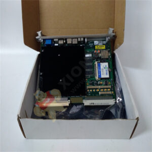
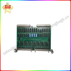
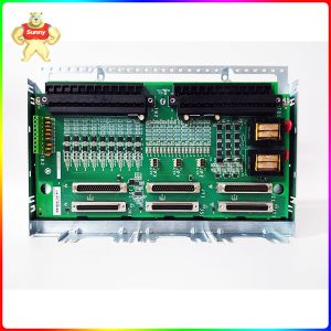
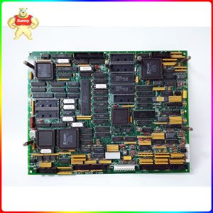
DS200TCQAG1BHF Analog I/O Board
Product Description
This DS200TCQAG1BHF Analog I/O Board from General Electric was originally, as mentioned above, manufactured for use in their Mark V Series of turbine control sytems and control system component products. This DS200TCQAG1BHF Analog I/O Board, as with any Mark V Series printed circuit board, makes use of a high number of product-unique and crucial hardware elements to achieve this intended functionality. Before attempting to purchase this DS200TCQAG1BHF Analog I/O Board, it is important to of course be cognizant of the fact that this DS200TCQAG1BHF Analog I/O or Input/Output Board makes use of its full possible range of additional product revisions; uniquely possessing both an H-rated secondary functional revision and an F-rated artwork revision.
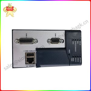
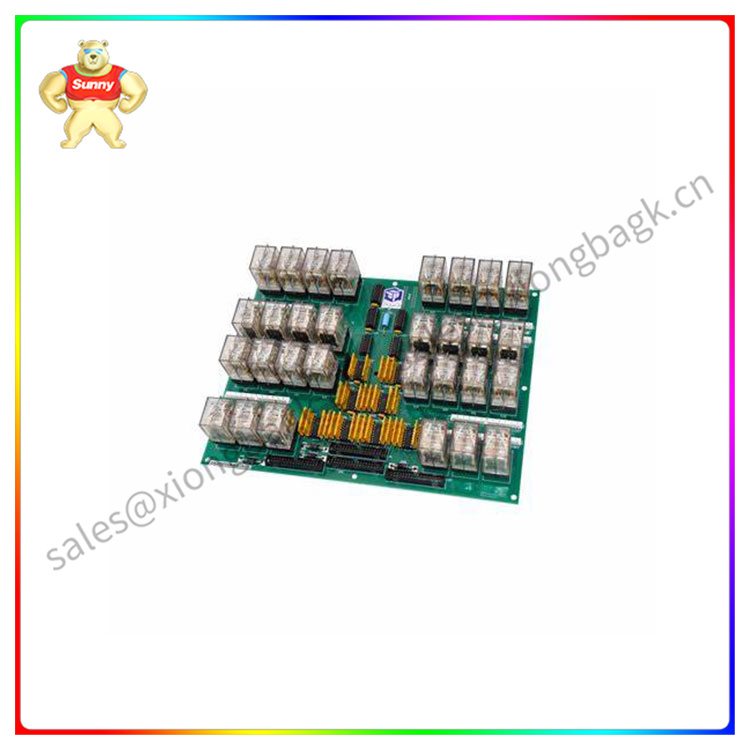
The GE RST Analog I/O Board DS200TCQAG1BHF contains four 34-pin connectors, two 40-pin connectors, and six jumpers. The board also has 6 LEDs. The GE RST Analog I/O Board DS200TCQAG1BHF is designed with 6 holes for installing the board in the board cabinet on the drive. The holes align with matching holes in the board rack and you can attach the board with washers and screws. When you remove the old board, it is of utmost importance to keep the washers and screws together for use when you install the replacement board. Due to the high voltage in the board, it is critical to not let any metal parts fall into the board cabinet. If a screw or washer falls in the cabinet, locate the part and remove it from the drive. It the drive is started with the loose metal still inside, the metal might damage the drive or start a fire or cause a serious electrical shock.
DS200TCRAG1ACC
Product parameter
| Manufacturer | GE General Electric |
| Series | Mark V |
| Part Number | DS200TCQAG1BHF |
| Product Description | Analog I/O Board |
| Functional Abbreviation | TCQA |
| PCB Coating | Normal Coating |
| Customizable Hardware | Manually-Movable Hardware Jumpers |
| Systems Used Alongside | <R> Core |
| Mark V Series Grouping | Group 1 |
Application field
Please contact Sunny sales@xiongbagk.cn for the best price.
➱ sales manager: Sunny
➱ email mailto: sales@xiongbagk.cn
➱ Skype/WeChat: 18059884797
➱ phone/Whatsapp: + 86 18059884797
➱ QQ: 3095989363
➱ Website:www.sauldcs.com