Description
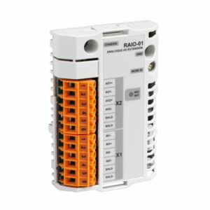
If you do not add the short-circuit terminal piece, the Address of the board
is 63=20+21+22+23+24+25, if the jumper to the above Address Pins and up, then the address
of the board is 0 jumper to X17 terminal 6D7.9.11.12 short-circuit, because the potential of 6 is
open, so, The corresponding 810 terminal is not shorted, and the input of 8.10 is regarded as
high voltage /logic1). Since the device connection point 8.10 corresponds to (NA1.NA3) and
corresponds to 21.23, the DeviceNet address of board /0 is 10=21+23
After figuring out the address of the board, it is necessary to configure the board on the instructor.
Find the configuration in the Control Panel
Find the Devicenet driver, click in, and select Add.
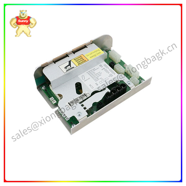
DSQC662
In the following menu DSCQ 652 board VDC I/O Device, set the default factory address of the
board seems to be 10. Click OK and the instructor will pop up a window telling you to restart the
computer. Add input signal in signal selection and set Device mapping(G area dynamic mapping).
Restart the computer input signal wiring
The robot control cabinet bought by the company is compact, and the power diagram OF the compact
cabinet can be found ON the ABB official website NO:3HAC049406-003. When the signal input terminal
flows current, the signal is checked by the OF as ON, so the DSCO652 board signal is defined as source
logic (that is, we say that the high level is effective).
Please contact Sunny sales@xiongbagk.cn for the best price.
➱ sales manager: Sunny
➱ email mailto: sales@xiongbagk.cn
➱ Skype/WeChat: 18059884797
➱ phone/Whatsapp: + 86 18059884797
➱ QQ: 3095989363
➱ Website:www.sauldcs.com