Description
Product details:
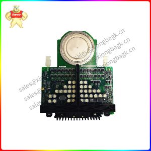
SCYC51020 58052582G trigger pulse board.Single-phase universal thyristor trigger board is a phase-shifting power controller which realizes voltage and current power adjustment of electrical equipment by adjusting the thyristor conduction Angle. Its core components are military grade thyristor trigger ASIC with high performance and high reliability produced abroad. The output trigger pulse has very high symmetry and stability, and does not change with the ambient temperature, there is no need to adjust the pulse symmetry and limit in use. Field debugging generally does not need oscilloscope to complete. It can be widely used in various industrial fields of voltage and current regulation, suitable for resistive load, inductive load, transformer primary side and a variety of rectifier devices
* The temperature control of nickel chromium, iron chromium aluminum, far infrared heating element and silicon molybdenum rod, silicon carbon rod as heating element.
* Salt bath furnace, power frequency induction furnace, quenching furnace, molten glass temperature heating control.
* Rectifier transformer, power regulating machine (pure inductor coil), primary side of electric furnace transformer, DC motor control.
* single phase welding machine, resistance welding machine, spot welding machine control and other tuning occasions.
* Single-phase fan pump speed control and energy saving control
* Voltage, current, power, light and other stepless smooth regulation.
The thyristor trigger circuit composed of a single junction transistor is shown in Figure 1, and the related voltage waveform of the trigger circuit is shown in Figure 2. Compared with the single junction transistor, the oscillation part of the circuit is the same. The synchronization is realized by improving the power supply circuit. The sinusoidal AC current of the autonomous circuit is depressurized by the synchronous transformer T to a lower AC voltage, and then becomes pulsating DC through the diode rectifier bridge. The role of the regulator VW and the resistance RW is “clipping”. When the pulsating voltage is less than the stable voltage value of the regulator, VW is not switched on, and the voltage at both ends is equal to the output voltage of the rectifier; If the pulsating voltage is greater than the stable voltage value of the regulator tube, VW will be broken down, and the voltage at both ends will remain the stable voltage value. The part of the output voltage of the rectifier bridge that is higher than the stable voltage value will fall to the resistance RW. In this way, the voltage waveform at both ends of VW is similar to a trapezoidal wave, which replaces the DC power supply in the tension oscillation circuit and plays a synchronous role.
Since the power supply of the oscillating circuit is trapezoidal wave, the power supply voltage of the oscillating circuit is very small, the circuit does not oscillate, and the capacitor voltage is released to 0 at the same time at the end and beginning of each half wave of the main circuit sine wave. When the power supply voltage is close to the top of the trapezoidal wave, the oscillating circuit starts to work. When the capacitor is charged so that the voltage at both ends reaches the peak voltage Vp of the single junction transistor, the single junction transistor conducts the current and discharge. The discharge current flows through the parallel circuit of R1 and the gate of the contacted thyristor to form an output, which provides the trigger pulse for the thyristor and makes the thyristor open. Then the circuit enters the next oscillation period, but the thyristor loses control once the gate is opened. The pulse output by the oscillating circuit in half a cycle of a supply voltage is only the first one to trigger, and the subsequent pulse is invalid. Near the end of the half cycle of the main circuit voltage, the power supply voltage of the oscillating circuit enters the hypotenuse of the trapezoidal wave and drops rapidly. The oscillating circuit stops vibrating and the capacitor voltage is released to 0. Therefore, in each half wave of the main circuit, the capacitor is always charged from 0, ensuring that the trigger pulse is synchronized with the voltage of the main circuit.
| MMS6310 | EPRO | MMS 6310 Dual channel key pulse monitor |
| MMS 6250 | EPRO | MMS6250 Shaft position monitor |
| MMS 6110 | EPRO | Axial vibration monitoring board MMS6110 |
| MMS 6140 | EPRO | MMS6140 vibration monitoring board |
| MMS 6210 | EPRO | MMS6210 displacement monitoring plate |
| MMS6220 | EPRO | MMS6220 eccentric monitoring plate |
| MMS6250 | EPRO | MMS 6250 Displacement plate |
| MMS 6250/D | EPRO | MMS6250/D Displacement plate |
| MMS6253/TS | EPRO | MMS 6253/TS DAPS mother board |
| MMS 6310 | EPRO | MMS6310 Key phase monitoring board |
| MMS 6312 | EPRO | MMS6312 speed monitoring board |
| MMS 6410 | EPRO | MMS6410 expansion monitoring board |
Please contact Sunny sales@xiongbagk.cn for the best price.
➱ sales manager: Sunny
➱ email mailto: sales@xiongbagk.cn
➱ Skype/WeChat: 18059884797
➱ phone/Whatsapp: + 86 18059884797
➱ QQ: 3095989363
➱ Website:www.sauldcs.com