Description
Product details:
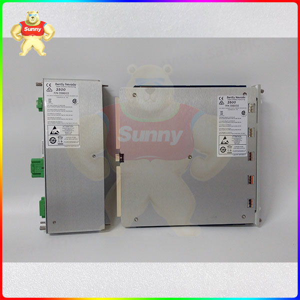
The 3500/22M Transient Data Interface (TDI) is the interface between the 3500 monitoring system and compatible software (system 1 condition monitoring and diagnosis software and 3500 system configuration software). tdi combines the capabilities of a 3500/20 rack interface module (RIM) with the data acquisition capabilities of a communications processor such as TDXnet. The TDI is installed in the slot adjacent to the power supply in cabinet 3500. It interfaces with the M series monitor (3500/40M,3500/42M, etc.) to continuously collect steady-state and transient dynamic (waveform) data and pass this data to the host software over the Ethernet link. See the Compatibility section at the end of this document for more information. Static data capture is a standard feature of TDI. However, using an optional channel-enabled disk will allow TDI to capture dynamic and high-resolution transient data. The TDI integrates communications processor capabilities within the 3500 rack. Although TDI provides certain functions common to the entire rack, it is not part of the critical monitoring path and has no impact on the normal operation of the overall monitoring system for automatic mechanical protection. One TDI or RIM is required for every 3500 rack, always occupying slot 1 (next to the power supply).
compatibility
When upgrading your 3500 rack from 3500/20 RIM to 3500/22 TDI, there may be 3500 M modules (e.g. 3500/40m) that are incompatible with 3500/22. More details are available at BNTechsupport.com.
3500/22M TDI Module and I/O
3500/22-AA-BB-CC
A: Transient Data Interface Type
01 Standard (use for standard monitoring
applications)
B: I/O Module Type
01 10Base-T/100Base-TX Ethernet
02 100Base-FX (Fiber Optic) Ethernet
03 10Base-T/100Base-TX Ethernet with
gold-plated OK Relay contacts
04 100Base-FX (fiber optic) Ethernet with
gold-plated OK Relay contacts
C: Agency Approval
00 None
01 CSA/NRTL/C (Class 1, Division 2)
02 Multi (CSA, ATEX, IECEx)
3500/22m dynamic data enable disk
This disk enables the number of dynamic data channels that TDI will support (that is, the ability to collect waveforms). There are two levels of dynamic data. Steady-state points are channels through which waveform data is collected as a result of software commands or alarm events, and therefore support current value, predetermined waveform capture, and alarm data capture. Transient points provide all the functionality of steady-state points with the additional ability to collect waveforms due to changes in parameters such as machine speed.
3500/09-AAA-BBB
A: Steady-State Points
000 to 672 Steady-State Points
B: Transient Points
002 to 672 Transient Points

3500/22M Ethernet cable
Standard 10 Base-T/100 Base-TX Shielded Class 5 cable with RJ-45 Connector (Solid Conductor)
138131-AAA
A: Cable Length
006 6 feet (1.8 m)
010 10 feet (3.0 m)
025 25 feet (12.2 m)
040 40 feet (12.2 m)
050 50 feet (15.2 m)
075 75 feet (22.9 m)
085 85 feet (25.9 m)
100 100 feet (30.5 m)
120 120 feet (36.6 m)
150 150 feet (45.7 m)
200 200 feet (61.0 m)
250 250 feet (76.2 m)
320 320 feet (97. m)
3500/22M optical fiber cable
100 Base-FX fiber optic cable with MT-RJ female connector.
161756-AAA
A: Cable Length in feet up to 1300 ft (400m)
010 to 500 10 ft. to 500 ft. in 10 ft. increments only
500 to1300 500 ft. to 1300 ft. in 100 ft.
increments only
Spares
288055-01 Standard Transient Data Interface Module with USB cable
123M4610* 10 foot A to B USB cable
146031-01 10Base-T/100Base-TX I/O Module
146031-02 100Base-FX (Fiber Optic) I/O Module
161580 3500/22M TDI Operation and Maintenance User Guide
164466 Network Accessories Datasheet
00580441 Connector header, internal termination, 3-position, green
00580436 Connector header, internal termination, 6-position, green
111M5777 Connector header, internal termination, 2-position, green
166M2390 Connector header, push-inspring type (alternative for PN 00580436)
166M4363 Connector header, push-inspring type (alternative for PN 00580441)

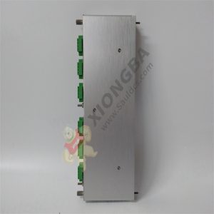
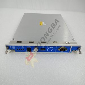
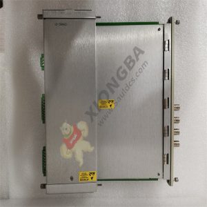
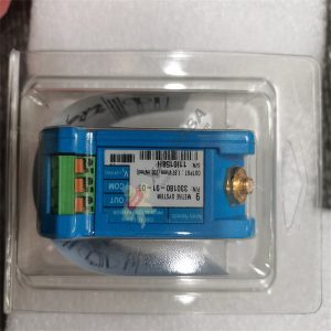
1. Main Module
2. 10 Base-T/100 Base TX (copper) Ethernet I/O Module
3. 100 Base-FX (fiber optic) Ethernet I/O Module
4. LEDs indicate operating status of the module
5. Hardware Switches
6. USB Configuration Port for configuring or retrieving
machinery data
7. OK Relay indicates the OK status of the overall rack
8. Signal Common external grounding terminal
9. RJ-45 Ethernet Port for configuration and data collection
10. System Contacts
11. Fiber Optic E

Recommended model:
Please contact Sunny sales@xiongbagk.cn for the best price.
➱ sales manager: Sunny
➱ email mailto: sales@xiongbagk.cn
➱ Skype/WeChat: 18059884797
➱ phone/Whatsapp: + 86 18059884797
➱ QQ: 3095989363
➱ Website:www.sauldcs.com