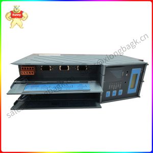
Description
8BVI1650HCS0.000-1 2 slots for ACOPOSmulti plug-in modules
1) Achievable safety classifications (safety integrity level, safety category, performance level) are documented in the user’s manual (section “Safety technology”).
2) Valid in the following conditions: 750 VDC DC bus voltage, 5 kHz switching frequency, 40°C ambient temperature, installation elevation <500 m above sea
level, no derating due to cooling type.
3) IM … Current on motor connection X5A [Aeff
]
4) PSLOT1 … Max. power consumption P8BAC [W] of the plug-in module in SLOT1 (see the technical data for the respective plug-in module)
PSLOT2 … Max. power consumption P8BAC [W] of the plug-in module in SLOT2 (see the technical data for the respective plug-in module).
P24 V Out … Power [W] that is output to connections X2/+24 V Out 1 and X2/+24 V Out 2 on the module (max. 10 W).
5) Valid under the following conditions: 750 VDC DC bus voltage, minimum permissible coolant flow volume (3 l/min).
6) The temperature specifications refer to the return temperature of the cold plate mounting plate.
7) Value for the nominal switching frequency.
8) The module cannot supply the full continuous current at this switching frequency. This unusual value for the return temperature, at which derating of the
continuous current must be taken into account, ensures that the derating of the continuous current can be determined in the same manner as at other
switching frequencies.
Caution! Condensation can occur at low flow temperatures and return temperatures.
9) The module cannot supply the full continuous current at this switching frequency. This unusual value for the ambient temperature, at which derating of the
continuous current must be taken into account, ensures that the derating of the continuous current can be determined in the same manner as at other
switching frequencies.
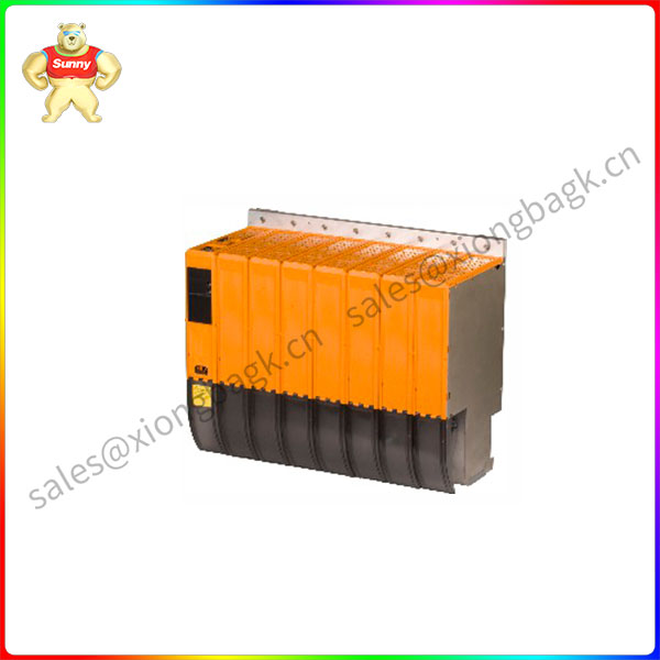
8BVI1650HCS0.000-1
10) B&R recommends operating the module at its nominal switching frequency. Operating the module at a higher switching frequency for application-specific
reasons reduces the continuous current and increases the CPU load.
11) If necessary, the stress of the motor isolation system can be reduced by an additional externally wired dv/dt choke. For example, the RWK 305 three-phase
du/dt choke from Schaffner (www.schaffner.com) can be used. Important: Even when using a dv/dt choke, it is necessary to ensure that an EMC-compatible,
low inductance shield connection is used!
12) The module’s electrical output frequency (SCTRL_SPEED_ACT * MOTOR_POLEPAIRS) is monitored to protect against dual use in accordance with Council
Regulation (EC) 428/2009 | 3A225. If the electrical output frequency of the module exceeds the limit value of 598 Hz uninterrupted for more than 0.5 s, then
the current movement is aborted and error 6060 is output (“Power unit: Limit speed exceeded”).
13) The connection is made with cable lugs for M8 (0.32″) threaded bolts. The nominal cross section of the cable lug must match the cross section of the conductor
that is to be connected in the particular application.
14) The maximum diameter that can be clamped depends on the shield component set.
15) During the project development phase, it is necessary to check if the minimum voltage can be maintained on the holding brake with the specified wiring. For
the operating voltage range of the holding brake, see the user documentation for the motor being used.
16) The specified value is only valid if the following requirements are met:
– The 24 VDC power supply for the module is provided by an auxiliary supply module 8B0C located on the same mounting plate.
– Connection between S1 and S2 (activation of the external holding brake) using a jumper with a max. length of 10 cm.
If the 24 VDC power supply for the module is applied to the mounting plate using an 8BVE expansion module, then the output voltage is reduced because
of voltage drops on the expansion cable. In this case, undervoltage monitoring must be disabled.
If jumpers longer than 10 cm are used to connect connectors S1 and S2, then the output voltage is reduced due to voltage drops on the jumpers.
17) OSSD (output signal switching device) signals are used to monitor signal lines for short circuits and cross faults.
18) Continuous operation at an installation elevation of 500 m to 4,000 m above sea level is possible taking the specified reduction of continuous current into
account. Requirements that go beyond this must be arranged with B&R.
19) Continuous operation at an ambient temperature of 40°C to max. 55°C is possible taking the specified reduction of continuous torque into account, but this
results in premature aging of components.
20) These dimensions refer to the actual device dimensions including the respective mounting plate. Make sure to leave additional space above and below the
devices for mounting, connections and air circulation.
Please contact Sunny sales@xiongbagk.cn for the best price.
➱ sales manager: Sunny
➱ email mailto: sales@xiongbagk.cn
➱ Skype/WeChat: 18059884797
➱ phone/Whatsapp: + 86 18059884797
➱ QQ: 3095989363
➱ Website:www.sauldcs.com