Description
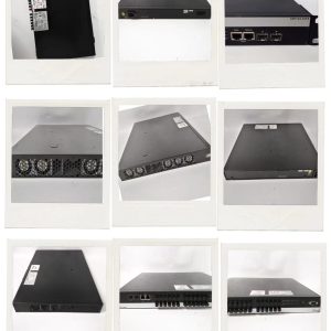
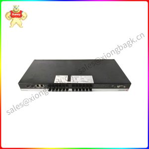
P0973JM X440-G2-12T8FX-GE4 X440-G2 series switches
This installation procedure applies to all optical transceivers. To install a transceiver in an X440-G2 Series switch:
1 Attach the ESD wrist strap to your wrist and connect the metal end to an appropriate ground point on the rack.
2 Remove the optical transceiver from the packaging.
3 If there is a protective dust cover on the connector, remove it at this time.
4 Hold the optical transceiver so that the connector will seat properly.
5 Carefully align the optical transceiver with the port slot.
6 Push the optical transceiver into the port slot until the transceiver clicks and locks into place.

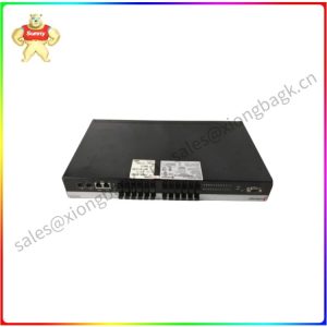
X440-G2-24FX-GE4
Otherwise, once you have connected power to the switch and verified LED activity, complete the setup process as follows:
1 Connect a management station to the console port using either an Ethernet to serial adapter or DB-9 serial cable.
2 Verify that the system LEDs are on (solid green or blinking green).
3 Using PuTTY, TeraTerm, or other terminal emulator, connect to the switch using the serial port connection. Be sure that your serial connection is set properly:
– 9600 baud
– 8 data bits
– 1 stop bit
4 Using the console session, perform the following:
a At the password prompt, press ENTER (RETURN) twice.
b Enter user: admin
c For the initial password, simply press ENTER.
d Follow the screen prompts for initial configuration.
e Enter the show version command. Record the switch serial number. The following is example output with the serial number in bold:
Transit.3 # show version
Please contact Sunny sales@xiongbagk.cn for the best price.
➱ sales manager: Sunny
➱ email mailto: sales@xiongbagk.cn
➱ Skype/WeChat: 18059884797
➱ phone/Whatsapp: + 86 18059884797
➱ QQ: 3095989363
➱ Website:www.sauldcs.com