Description
DS200SDCIG1ABA Technical Specifications
Manufacturer GE General Electric
Series Mark V
Part Number DS200SDCIG1ABA
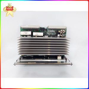
Product Type SDCI DC Power Supply and Instrumentation Board
Instruction Manual GEI-100173
Product Description
The GE DC Power Supply and Instrumentation Board DS200SDCIG1ABA serves as an interface to DC2000 drives.
Service and periodic maintenance must be performed on the DS200SDCIG1ABA only by qualified individuals. That i
s, don’t attempt to remove and replace the board yourself because of the high-voltage present in the drive and the bo
ard. You could unknowingly damage the board by allowing the board to touch components in the drive cabinet or dam
age cables by using an incorrect method to remove the cables.
Safety is of the highest concern. If you don’t take the proper precautions to remove all power from the board before to
uching it, a serious electric shock or burn might occur.
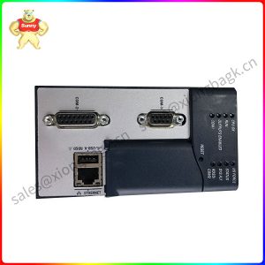
There is one troubleshooting task you can perform yourself. You can open the cabinet and view the LED indicators on
the board with power present in the drive and board. If an LED indicator is lit it indicates that the fuse associated with
the LED is blown. However, you must not touch the board or any components in the drive.
If you see a blown fuse and you want to remove the board, you must perform the following procedure. Not only must
you switch off the drive but you have to remove the fuses on the 3-phase power supplies. Also make sure to remove
the auxiliary power supply as well. Wait several minutes for power to exit the board. Before you proceed, use a tester
device to verify that there is no power present in the board.
 DS200SDCIG1ABA
Frequently Asked Questions about DS200SDCIG1ABA
Can you remove connections on DS200SDCIG1ABA while DS200SDCIG1ABA is operating?
No, you should not remove connections or boards on DS200SDCIG1ABA or re-insert them to DS200SDCIG1ABA while power is applied to DS200SDCIG1ABA. If done, there may be equipment damage to DS200SDCIG1ABA.
What is the JP1 jumper on DS200SDCIG1ABA?
Jumper JP1 on DS200SDCIG1ABA is the MD control source jumper that allows the MD contactor drive hardware output to be slaved to the MA contactor drive hardware output on DS200SDCIG1ABA. Normally on DS200SDCIG1ABA, the MD contactor drive output is controlled independently by MCP software.
What is DS200SDCIG1ABA used for?
DS200SDCIG1ABA is used to provide logic power and interface circuitry for DC2000 drives with input voltages up to 600 VAC.
Where can I find the manual for DS200SDCIG1ABA?
We can send you the link to the manual for DS200SDCIG1ABA. The manual for DS200SDCIG1ABA is the GE Drive Systems Replacement Procedures for SDCI DC Power Supply and Instrumentation Board Manual, a manual directly specific to DS200SDCIG1ABA. You can also receive a hard copy of the manual for DS200SDCIG1ABA upon request for the manual.
This board has multiple circuits on its surface including drive circuits for armature SCR gating and others for different AC and DC line motor signals. The board also includes motor field power circuits. It is designed to work within DC2000 drives (up to 600 VAC). Read through GE manuals and user guides for additional information.
Please contact Sunny sales@xiongbagk.cn for the best price.
➱ sales manager: Sunny
➱ email mailto: sales@xiongbagk.cn
➱ Skype/WeChat: 18059884797
➱ phone/Whatsapp: + 86 18059884797
➱ QQ: 3095989363
➱ Website:www.sauldcs.com