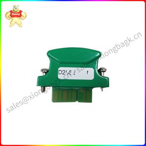
Description
G772K240A G77X/77X Series Electrohydraulic Servo valve
1. INTRODUCTION
This manual provides instructions and procedures necessary to install, operate and troubleshoot the Moog Inc. Series G771/G772/G773
(simplified as G77X) and 771/772/773 (simplified as 77X) Electrohydraulic
Industrial Servovalve.Troubleshooting instructions are outlined to permit the identification of the specific component(s) suspected of failure.
2. OPERATION
The Moog G77X/77X Series Industrial Servovalve consists of a polarized electrical torque motor and two stages of hydraulic power amplification.The
motor armature extends into the air gaps of the magnetic flux circuit and is supported in this position by a flexure tube member.The flexure tube acts as a
seal between the electromagnetic and hydraulic sections of the valve.The two motor coils surround the armature, one on each side of the flexure tube.
The flapper of the first stage hydraulic amplifier is rigidly attached to the midpoint of the armature.The flapper extends through the flexure tube and
passes between two nozzles, creating two variable orifices between the nozzle tips and the flapper.The pressure controlled by the flapper and nozzle variable
orifice is fed to the end areas of the second stage spool.
The second stage is a conventional four-way spool design in which output flow from the valve, at a fixed valve pressure drop, is proportional to spool
displacement from the null position. A cantilever feedback spring is fixed to the flapper and engages a slot at the center of the spool. Displacement of the spool
deflects the feedback spring which creates a force on the armature/flapper assembly.
Input signal induces a magnetic charge in the armature and causes a deflection of the armature and flapper.This assembly pivots about the flexure
tube and increases the size of one nozzle orifice and decreases the size of the other.
This action creates a differential pressure from one end of the spool to the other and results in spool displacement.The spool displacement transmits a
force to the feedback wire which opposes the original input signal torque. Spool movement continues until the feedback wire force equals the input signal force.

G772K240A
To prolong servovalve operational life and to reduce hydraulic system maintenance, it is recommended that the hydraulic fluid be kept at a cleanliness
level of ISO DIS 4406 Code 16/13 maximum, 14/11 recommended.The most effective filtration scheme incorporates the use of a kidney loop or “off-line”
filtration as one of the major filtration components.The filter for the “off-line” filtration scheme should be a ß3≥75 filter for maximum effectiveness.
Upon system startup and prior to mounting the servovalve, the entire hydraulic system should be purged of built-in contaminating particles by an
adequate flushing.The servovalve should be replaced by a flushing manifold and the hydraulic circuit powered up under conditions of fluid temperature and fluid
velocity, reasonably simulating normal operating conditions. New system filters are installed during the flushing process whenever the pressure drop across the
filter element becomes excessive.The flushing processes should turn over the fluid in the reservoir between fifty to one hundred times.
To maintain a clean hydraulic system, the filters must be replaced on a periodic basis. It is best to monitor the pressure drop across the filter assembly
and replace the filter element when the pressure drop becomes excessive. In addition to other filters that are installed in the hydraulic circuit, it is
recommended that a large capacity, low pressure ß3≥75 filter be installed in the return line. This filter will increase the interval between filter element
replacements and greatly reduce the system contamination level.
Please contact Sunny sales@xiongbagk.cn for the best price.
➱ sales manager: Sunny
➱ email mailto: sales@xiongbagk.cn
➱ Skype/WeChat: 18059884797
➱ phone/Whatsapp: + 86 18059884797
➱ QQ: 3095989363
➱ Website:www.sauldcs.com