Description
BE3-25A Auto-Synchronizer provides automatic synchronization

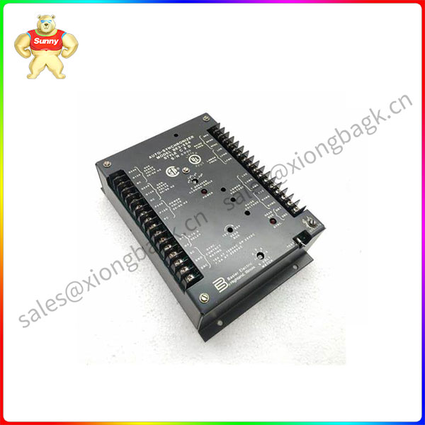
a. General Description. The Basler BE3-25A Auto-Synchronizer provides automatic synchronization of an oncoming generator with a bus or another generator. The Synchronizer
supplies correction signals to the oncoming generator to match it to the bus or to another generator for frequency, phase angle, and voltage before being closed into the circuit. Options allow for dead
bus closing and a variety of output configurations for frequency/phase matching and voltage matching. Construction consists of a case enclosed circuit board with external terminal connections.
A TEST/OPERATE switch, LED SYNC and POWER indicators and all operational adjustments are located on the front panel or are accessible through access holes in the front panel.
b. Basic Unit Description.
(1) The basic BE3-25A Auto-Synchronizer monitors both the oncoming generator and bus
voltages then permits synchronizing the generator to an energized station bus or to another generator when the following predetermined conditions are satisfied:
(a) The frequency of the oncoming generator and the bus are matched to within ±0.1 Hertz.
This corresponds to a slip frequency of ±0.1 Hertz or less.
(b) The phase angle between the oncoming generator voltage and the bus voltage is less than or equal to the allowable limit determined by the front panel setting. This limit is
established by the position of the front panel BREAKER CLOSING ANGLE switch with settings of ±5°, ±10°, ±15°, and ±20°.
(c) The difference between the generator and bus voltage is less than the selected voltage difference setting which is continuously adjustable over the range of ±5% to ±15% of the
bus voltage.
(2) When a jumper is connected across the 0.75 Second Time Delay terminals of the Synchronizer (terminals D1 and D2), the generator will be synchronized only when the generator output
voltage is within the selected voltage difference setting and the measured phase angle and difference (slip) frequency are less than the following:
BE3-25A
When the phase angle, frequency, and voltage are within predetermined limits, the Synchronizer energizes the isolated synchronizing output relay to initiate generator circuit breaker closure.
The front panel SYNC indicator will illuminate and the frequency and phase angle correction signals are automatically reset. The correction signals can be reset manually by connecting a normally open
contact between the Reset terminals of the Synchronizer (terminals R1 and R2). Closure of the synchronizing output relay within the synchronizing parameters will automatically reset the correction
output signals.
(4) Upon a loss of power (power input falls below 85 Vac for 50 and 60 Hertz systems) or removal of either the bus or generator sensing input voltage, the Synchronizer will immediately
remove all output correction signals to the governor or voltage regulator.
(5) A built-in “operational test” mode can be used to verify Synchronizer operation when connected to the generator. The Sync Output Relay is inhibited from operating when the
TEST/OPERATE switch is set to the TEST position. A red LED (SYNC) on the front panel will
illuminate whenever the frequency, phase angle, and voltage are all within the contact closure parameters.
Please contact Sunny sales@xiongbagk.cn for the best price.
➱ sales manager: Sunny
➱ email mailto: sales@xiongbagk.cn
➱ Skype/WeChat: 18059884797
➱ phone/Whatsapp: + 86 18059884797
➱ QQ: 3095989363
➱ Website:www.sauldcs.com