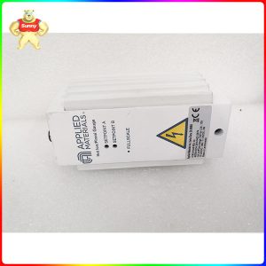
Description
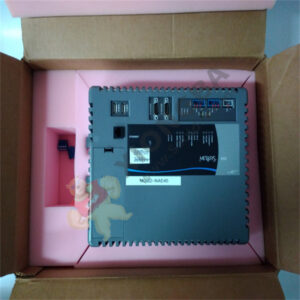
DYNAMIC BRAKING UNIT DBU-400 INVERTRON DBU Dynamic Braking Unit
Product description
Frequency converters (Inverters) with DC bus and input diode rectifier bridge are suitable for the operation of three phase AC-motors in two drive quadrants, motoring in both directions of rotation.
Braking with more than 10% of the rated inverter current is only possible with a braking unit.
Without a braking unit, an excessively rapid deceleration causes an increase in the DC bus voltage.
The regulator responds by
• shut-down due to DC bus overvoltage tripping (e.g. on GV3000: Fault HU)
• extending the set deceleration rate or increasing the output frequency depending on parameter setting.
By the use of a Dynamic Braking Unit (DBU) and braking resistor the energy in the DC bus circuit can be converted to heat.
After removing the cover plate of the DBU the blue jumper plug with positions 460V / 415V is accessible at the upper edge of the regulator card (middle on BUC, right on BUA).
This jumper plug defines the DC bus voltage at which the DBU switches the DB resistor to the DC bus.
When delivered from stock the DBU is adjusted for safety reasons to 460 V line voltage.
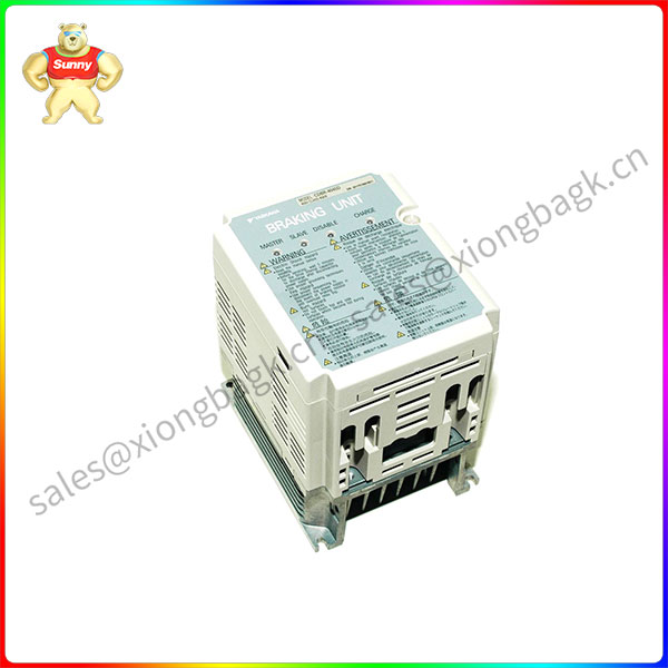
DYNAMIC BRAKING UNIT DBU-400
Product parameter
For the Inverters INVERTRON VTI / VCI / VGI type 415 V the blue jumper plug must be changed from position 460 to 415.
Reason: On these inverters the max. permissible DC bus voltage is DC 720 V.
This fault trip level is fixed and assigned to the power semiconductors. It requests a DBU turn-on voltage of 680 V, corresponding to 415 Vac line voltage selection.
For the GV3000 Inverters on line voltages up to 415 V the blue jumper plug must be set to position 415.
For the GV3000 Inverters on line voltages above 415 V and all the other inverters VTI / VCI / VGI type 460 V, GMI, GP2000 and SP500 the jumper must stay in position 460.
Application field
To prevent thermal overload of the Braking Unit, assure that the unit works within the following limits:
In a time range of 10 minutes the permissible loading must be limited to the following current-time area of any shape Imax x 2.5 minutes, with the following exception:
On DBU-400 current loading Imax (400 A) is permitted for 110 seconds every 10 minutes.
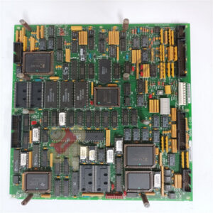
The diagnostic card BUD, (part No. 813.02.00) is incorporated on units DBU-xx-DIS and all DBU-400.
On units DBU-xx (with PWM-regulator BUC) the diagnostic card option set DBU-DIS (Part No. 839.25.41) can be built in on site or used as a replacement part.
On DBU-400 units the BUD card is always built-in as a standard.
The BUD works independent from the DBU regulator based on separate DC bus voltage feedback values and the voltage across the DB resistor. It replaced the DBU indication card BUB (set 839.25.00) and contains besides the DC bus voltage and braking current indications two additional diagnostic functions (available at terminals).
Indications
• DC bus voltage: left LED lights when UDC > 50 V
• braking current : right LED lights when IB > 0
Switched output S1-2 (UDC > 50V)
Wearless transistor switch between terminals 1 (-) and 2 (+)
• S1-2 is closed, when UDC > 50 V and IB = 0
• S1-2 is open, when UDC > 50V and IB > 0, or when UDC < 50 V.
As shown in figure 2-4, switch S1-2 is closed after charging of the DC bus, at motor stand still or in motoring operation mode.
Please contact Sunny sales@xiongbagk.cn for the best price.
➱ sales manager: Sunny
➱ email mailto: sales@xiongbagk.cn
➱ Skype/WeChat: 18059884797
➱ phone/Whatsapp: + 86 18059884797
➱ QQ: 3095989363
➱ Website:www.sauldcs.com


 中文版
中文版

