中文版
中文版

Description
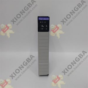
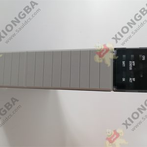
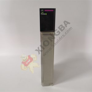
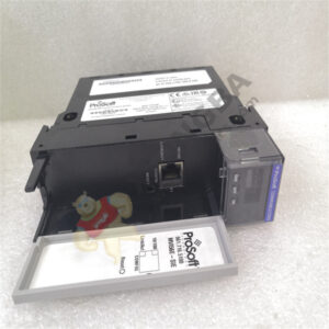
MVI56E-MCM ControlLogix® Platform Modbus Communication Module
Product description
To get the most benefit from this User Manual, you should have the following skills:
Rockwell Automation® RSLogix™ software: launch the program, configure ladder logic, and transfer the ladder logic to the processor
Microsoft Windows®
: install and launch programs, execute menu commands, navigate dialog boxes, and enter data
Hardware installation and wiring: install the module, and safely connect Modbus and ControlLogix devices to a power source and to the MVI56E-MCM module’s application port(s)
The Setup Jumper acts as “write protection” for the module’s firmware. In “write protected” mode, the Setup pins are not connected, and the module’s firmware cannot be overwritten. The module is shipped with the Setup jumper OFF. Do not jumper the Setup pins together unless you are directed to do so by ProSoft Technical Support (or you want to update the module firmware).
The following illustration shows the jumper configuration with the Setup Jumper OFF. 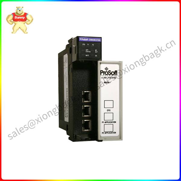
Product parameter
Read/Write Ethernet Configuration
Allows the processor to read or write the module IP address, subnet mask, and network gateway IP address.
Read/Write Module Clock Value
Allows the processor to read and write the module clock settings. The module’s freerunning clock also stores the last time that the Ethernet configuration was changed or the last time the module was restarted or rebooted. The date and time of the last change or restart is displayed on the scrolling LED during module power-up/start-up sequence.
Application field
Make sure your ControlLogix processor and power supply are installed and configured, before installing the MVI56E-MCM module. Refer to your Rockwell Automation product documentation for installation instructions.
After you have checked the placement of the jumpers, insert the MVI56E-MCM into the ControlLogix chassis. Use the same technique recommended by Rockwell Automation to remove and install ControlLogix modules.
You can install or remove ControlLogix system components while chassis power is applied and the system is operating. However, please note the following warning.
1 Align the module with the top and bottom guides, and then slide it into the rack until the module is firmly against the backplane connector.
2 With a firm, steady push, snap the module into place.
3 Check that the holding clips on the top and bottom of the module are securely in the locking holes of the rack.
4 Make a note of the slot location. You must identify the slot in which the module is installed in order for the sample program to work correctly. Slot numbers are identified on the green circuit board (backplane) of the ControlLogix rack.
5 Turn power ON.
Please contact Sunny sales@xiongbagk.cn for the best price.
➱ sales manager: Sunny
➱ email mailto: sales@xiongbagk.cn
➱ Skype/WeChat: 18059884797
➱ phone/Whatsapp: + 86 18059884797
➱ QQ: 3095989363
➱ Website:www.sauldcs.com