中文版
中文版

Description
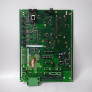
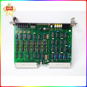
Excitation controller GFD563A101 3BHE046836R0101 Working principle:
Exciting device GFD563A101 3BHE046836R0101 main circuit part
Composition and function of the main loop
The main circuit of the device completes the two functions of rectification and demagnetization.
The system adopts three-phase fully controlled bridge thyristor rectifier circuit to provide
DC excitation current to the rotor winding of synchronous motor.
The degaussing circuit is composed of thyristor 7, 8KGZ and diode GZ in inverse parallel, and actually consists of
a high-power electronic switch, which completes the serial starting resistance of synchronous motor in the process
of asynchronous starting, and automatically cuts it out after the end of starting, so as to ensure that the rotor
excitation winding is neither open nor short circuit during the asynchronous starting of synchronous motor.
So as to avoid the field winding under overvoltage and overcurrent.
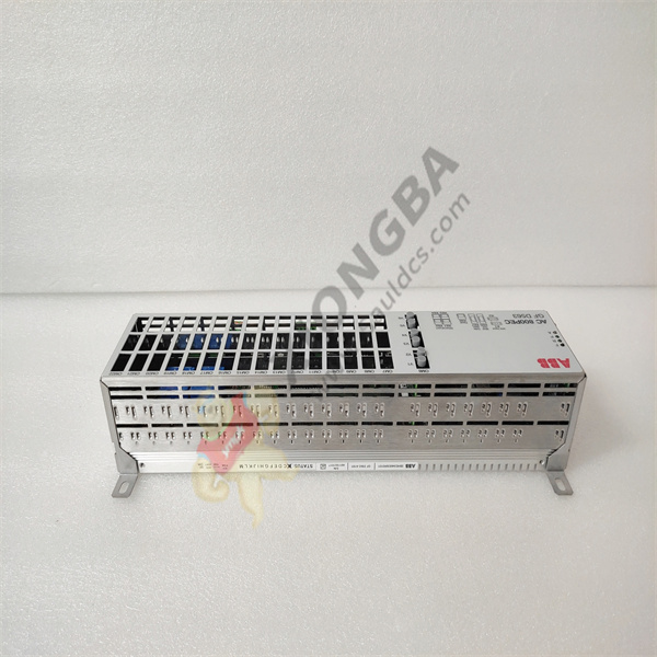
GFD563A101 3BHE046836R0101
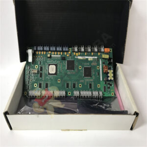
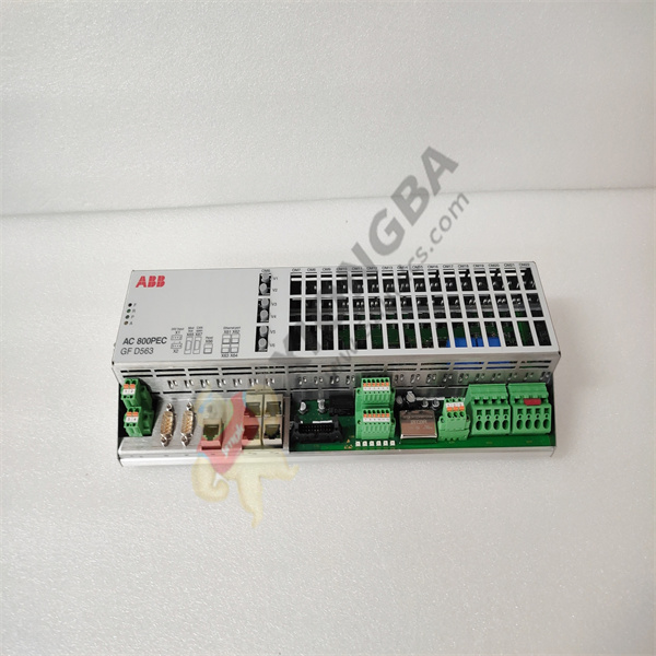
Exciting device control GFD563A101 3BHE046836R0101 Part:
GFD563A101 3BHE046836R0101 System control part includes S7200PLC, Pro-face touch screen,
KGLF-2 microcomputer excitation controller composed of three parts. PLC is mainly responsible
for the switching of the working mode of the relay loop logic control, the adjustment of PI during operation and external communication, etc.
Pro-face touch screen is mainly responsible for the system parameter setting and the query of the information of faults during operation, working time and set operation parameters.
Pro-face touch screen has the information of excitation current and excitation voltage recording curve.
KGLF-2 excitation controller GFD563A101 3BHE046836R0101 by the host MC87C51 and auxiliary AT89C51 microcontroller composed.
Excitation controller mainly completes frequency measurement and excitation, pulse formation, fault detection and processing.
GFD563A101 3BHE046836R0101
Measurement of rotor induced voltage frequency
When the synchronous motor starts, the frequency of the rotor induced voltage decreases gradually with the rise of the speed.
Once the synchronous motor starts, the MCU immediately detects the time of the rotor induced half a cycle wave.
From 20ms, the digital tube is marked “9”, and every 20ms in the middle, the digital tube is reduced by 1.
In the process of asynchronous starting, when the rotor speed reaches 90% of the synchronous speed,
the rotor induced voltage frequency is 5Hz, the cycle is 0.2s, and the half cycle time is 100ms.
Once the computer detects the value, it will immediately throw the full voltage.
After the full voltage is applied, the motor’s speed will continue to rise. When the speed increases to 95% of the synchronous speed,
the rotor induced voltage frequency is 2.5Hz, the period is 0.4s, and the half cycle time is 200ms. The computer detects this value.
Quickly enter the rectifier procedure, output pulse, device into the excitation, at the same time through the excitation work instructions,
turn off low voltage magnetization and open the loss of magnetic protection and out of step protection.
2 Pulse formation
GFD563A101 3BHE046836R0101
Synchronization signals Ta and W3 provide positive offset and output signal Uk of excitation regulator.
After comprehensive processing by operational amplifier, these three signals are used as input signals of external interrupt request INT0 of the single chip microcomputer.
When INT0 changes from 1 to 0, the single chip accepts the interrupt and immediately sends out the first set of pulses to trigger 1# thyristor and fill a pulse to 6# thyristor.
Then the next set of pulses will be sent every 60° to trigger the corresponding thyristor until the six sets of pulses are sent out in one cycle,
and then wait for the next interruption. To change the size of the Uk have changed time of interrupt application, achieve the goal of control Angle .
In order to improve the symmetry of the rectifier voltage waveform,
the system also continuously monitors the frequency of the power grid and corrects the 60° timing at any time to ensure the symmetry of the rectifier voltage waveform.
In this way, the pulse generated is of high precision, without external adjustment, and stable and reliable.
3 Fault Protection
The system has input power supply circuit breaker, power supply phase off, fast melting, under magnetic, out of step, over current, starting time out and other protection.
These faults are mainly monitored and detected by the auxiliary engine.
Once the fault is confirmed, the auxiliary engine immediately notifies the main control computer.
After receiving the signal, the main engine quickly makes the corresponding fault treatment,
sends out the fault display and sound signal, connects the high-voltage oil breaker switching circuit,
and synchronizes the motor to stop in an emergency. At the same time, the system pushes β inverter operation to feed the energy stored in the excitation winding back to the grid,
and block the pulse after a delay of 5 ~ 6s.
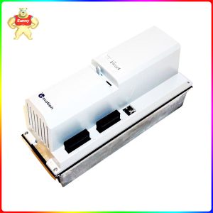
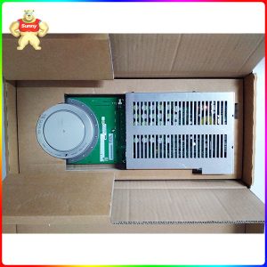
Please contact Sunny sales@xiongbagk.cn for the best price.
➱ sales manager: Sunny
➱ email mailto: sales@xiongbagk.cn
➱ Skype/WeChat: 18059884797
➱ phone/Whatsapp: + 86 18059884797
➱ QQ: 3095989363
➱ Website:www.sauldcs.com