中文版
中文版

Description
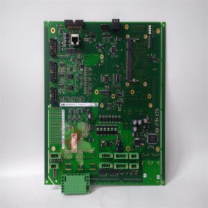
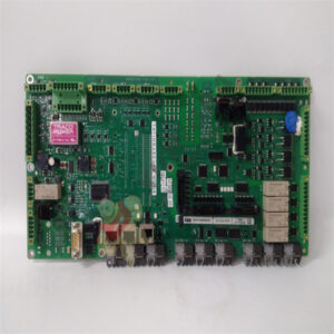
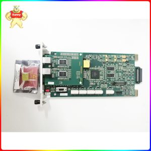
SPAU 341 C1-AA SPAU 341 C Voltage regulator
Product Description
The voltage regulator SPAU 341 C is intended to be used for regulating the voltage of power transformers with on-load tap-changers in distribution substations. The connections required for a simple voltage regulating function is the measured phase-to-phase voltage U12 and the raise and lower output contacts. If the line drop compensation, the minimizing circulating current or the overcurrent blocking feature is to be used, one or more phase currents have to be measured. If only one phase current is measured, it is always connected to the terminals of the phase current I L1, and the current to be measured is selected with the software switches SGF2/6 and SGF2/7 of the automatic voltage regulating module SPCU 1D50.
The purpose of the regulator is to maintain a stable secondary voltage of the power transformer. The basis for this operation is the reference voltage, which is set by the user. By adding
or decreasing various compensation factors, the regulator calculates a control voltage from the reference voltage. Hence, the control voltage is the desired transformer secondary voltage to be maintained by the regulator. Then the control voltage is compared with the voltage measured and the difference between these two forms the regulating process error.
Since the tap-changer changes the voltage in steps, a certain error has to be allowed. This error, called bandwidth, is also set by the user. If the measured voltage fluctuates within the bandwidth, the regulator is inactive. Should, on the other hand, the measured voltage be outside these bandwidth limits, an adjustable delay T1 starts. This delay T1 remains active as long as the measured voltage is outside the hysteresis limits of the bandwidth. The factory setting of the hysteresis limits is 90%.
Should the measured voltage still be outside the hysteresis, when the delay counter T1 reaches its setting value, the raise or lower output relay is activated and the motor drive of the tapchanger is operated. If, on the other hand, the measured voltage falls within the hysteresis limits, the delay counter is reset.
Should one tap-changer operation not be enough to regulate the transformer voltage within the hysteresis limits, a second adjustable delay T2, usually with a shorter time setting than T1, starts.
The delays T1 and T2 can be selected either with definite or inverse time characteristic. Inverse time characteristic means, that the delay is inversely proportional to the regulator error, i.e the delay is inversely proportional to the difference between the control voltage and the measured voltage.
The voltage regulating function will be described more in detail in the document 1MRS 750111- MUM EN.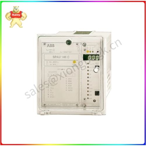
Product parameter
Block Blocking of regulating function, input
Uaux Auxiliary voltage, input
RSV Reduce set voltage or parallel input
AUT/MAN Automatic or manual mode, output
IRF Self-supervision signal, output
RAISE Raise signal, output
LOWER Lower signal, output
I> Overcurrent or overvoltage blocking, output
U< Undervoltage blocking output
SERIAL PORT Serial communication port
TAP POS Tap-changer position input, mA signal
TCO Tap-changer operating input
RAISE’ Raise command or parallel operation input
LOWER’ Lower command or reduce set voltage input
AUTO’ Automatic mode input
MAN’ Manual mode input
U1 Automatic voltage regulating module SPCU 1D50
U2 Manual voltage regulating module SPCN 1D56
U5 I/O module
U6 Energizing input module
SPA-ZC_ Bus connection module
Rx/Tx Fibre-optic receiver (Rx) and transmitter (Tx) of the bus connection module
Application field
The power supply module is located behind the system front panel of the regulator and can be withdrawn after removal of the system front panel. The power supply module produces the voltages required by the regulating modules from the auxiliary voltage.
There are two types of power supply modules,
differing only in input voltage:
SPGU 240 A1:
Rated voltage Un = 110/120/230/240 V ac
Un = 110/125/220 V dc
Operative range U = 80…265 V ac/dc
SPGU 48 B2:
Rated voltage Un = 24/48/60 V dc
Operative range U = 18…80 V dc
Which power supply the regulator contains, is marked on the system panel.
The power supply module is a transformer-connected, i. e. galvanically separated primary and secondary circuits, flyback type rectifier. The primary circuit is protected by a 1 A fuse, F1 (slow), in SPGU 240 A1, and a 4 A fuse (fast) in SPGU 48 B2. The fuses are located on the circuit board of the module.
When the power supply module is operating, the green LED indicator Uaux on the system panel is lit. The supervision of the supply voltages for the electronics is incorporated into the regulating modules. A self-supervision alarm is given if one of the secondary voltages differs by more than 25% from the rated value. An alarm signal is also obtained, if the power supply module is missing, or if the auxiliary voltage to the regulator has been interrupted.
Please contact Sunny sales@xiongbagk.cn for the best price.
➱ sales manager: Sunny
➱ email mailto: sales@xiongbagk.cn
➱ Skype/WeChat: 18059884797
➱ phone/Whatsapp: + 86 18059884797
➱ QQ: 3095989363
➱ Website:www.sauldcs.com