

Description
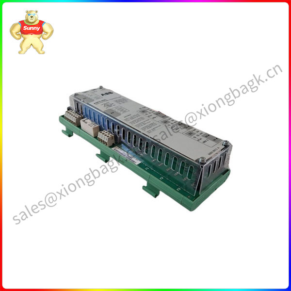
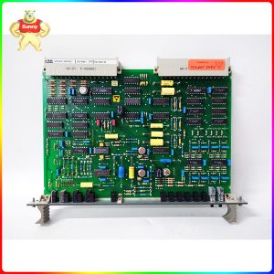
NX2A4T-11 Four Channel Modbus TCP/IP Resolver Input Module
This chapter shows an overview of the BSFC units and describes the connectors, settings
and LEDs. In addition, it contains circuit diagram examples of the DC supply circuit of
ACS880 frame R8i modules, and describes switch-on and switch-off sequences of the units.
Overview
ACS880 frame size R8i inverter modules can be connected to the drive DC bus through a
disconnector (or fuse-switch). This configuration requires a charging circuit to charge the
DC capacitors of the modules in a controlled way. The DC voltage can be directly connected
to the modules only after the capacitors are charged to a sufficient level. The BSFC is a unit
that monitors the charging, and controls switch-on and switch-off of the DC voltage.
In addition to inverter units, the BSFC can be used with other units consisting of R8i modules,
such as brake or DC/DC converter units. One BFSC unit can control the charging of up to
3 frame R8i modules.
The BSFC unit can be installed onto a standard mounting rail.
BSFC-02C
The terms and designations used in the table below refer to the diagrams in section
Connections of the DC supply circuit.
1. User turns charging switch [Q10] to position 1 (ON).
• Charging of the inverter capacitors starts through the charging resistors [R10]:
• Auxiliary contact 1-2 of charging switch [Q10] opens.
• BSFC prevents the starting of inverters and the closing of DC
switch-disconnector [Q11].
• BSFC monitors inverter UDC signals through fiber optic link(s) INV1…INV3.
• INV STAT and PWR LEDs are on.
• When the charging is complete (inverter DC voltage over 80% of nominal):
• BSFC receives a UDC signal from the inverter(s).
• BSFC connects operating voltage to the solenoid of DC switch-disconnector
[Q11]. The solenoid releases the locking mechanism, allowing operation of the
handle.
• INV UDC and PWR LEDs are on.
• The Charging OK light [P11] on the cabinet door is on, indicating that the
operation of the DC switch-disconnector [Q11] is allowed.
2. User turns DC switch-disconnector [Q11] to position 1 (ON).
• Main contacts 1-2…7-8 of DC switch-disconnector [Q11] connect inverter(s) to DC
power supply.
• Auxiliary contact 13-14 of DC switch-disconnector [Q11] closes.
• Auxiliary contact 21-22 of DC switch-disconnector [Q11] opens, de-energizing the
solenoid. The Charging OK light [P11] on the cabinet door goes off.
• INV UDC and PWR LEDs are on.
3. User turns charging switch [Q10] to position 0 (OFF).
• BSFC receives a “main switch ON, charging switch OFF” signal through terminal
AUX2.
• BSFC sends an enable signal to inverter through the fiber optic link.
• INV UDC and PWR LEDs are on.


Please contact Sunny sales@xiongbagk.cn for the best price.
➱ sales manager: Sunny
➱ email mailto: sales@xiongbagk.cn
➱ Skype/WeChat: 18059884797
➱ phone/Whatsapp: + 86 18059884797
➱ QQ: 3095989363
➱ Website:www.sauldcs.com


Reviews
There are no reviews yet.