Description
DS200TBQCG1AAA Technical Specifications
Part Number DS200TBQCG1AAA
Series Mark V
Manufacturer GE General Electric
Instruction Manual GEH-6153
Product Type RST Analog Termination Board
Functional Acronym/Abbreviation TBQC
Number of TBQC Connections 5; JBR, JFR, TEST, JBS/T, and JFS/T
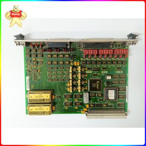
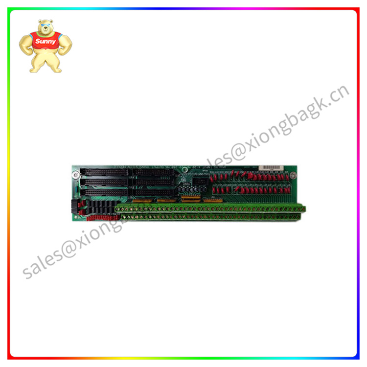
Product Description
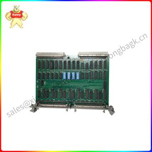
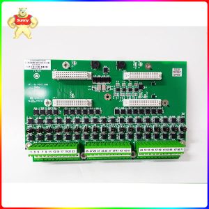
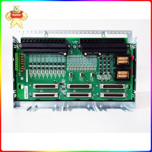
The GE RST Analog Termination Board DS200TBQCG1AAA features two terminal blocks. Each block contains eighty-three terminals for signal wires. The GE RST Analog Termination Board DS200TBQCG1AAA also contains 15 jumpers, three 40-pin connectors, and three 34-pin connectors. The jumpers enable the servicer to modify the behavior of the board to meet the exact requirements of the drive operation. When you first setup the board and have received the board from the factory, refer to the installation instructions which will include a description of the jumpers and how the position of the jumpers modifies the operation of the board. The jumpers are in the default position when you receive the board. The default is used for most situations and no additional steps are required if the default value is all you require.
The 3-pin jumper is easy to move from the default position to the alternate position. Use your forefinger and thumb to remove the jumper from the default position. Then align the jumper over the alternate pins and press the jumper into place. For example, if pins one and two are the default position in a 3-pin jumper, insert the jumper over pins two and three to use the alternate position.
Some jumpers on the DS200TBQCG1AAA unit are for use by the factory only and cannot be changed. Typically the alternate position is for use at the factory for quality control testing purposes only. When you replace the board, first move the jumpers on the replacement board to match the positions on the defective one.
Frequently Asked Questions about DS200TBQCG1AAA
What type of output signals does DS200TBQCG1AAA have?
The signals on the DS200TBQCG1AAA board are milliamp output signals. These signals will go to or come from the attached TCQA board in its respective core. The output type associated with this model and the TCQA boards is 20-200 mA outputs.
What are the input signals on DS200TBQCG1AAA?
The input signals for the DS200TBQCG1AAA board are the same as the output signals, which are milliamp signals. The milliamp signals that are available on this board are LVDT/R position inputs and 4-20 mA to the attached TCQA and its respective core.
What are jumpers BJ1 through BJ15 for on DS200TBQCG1AAA?
Jumpers BJ1 through BJ15 on DS200TBQCG1AAA are for connecting the milliamp input signals 1-15 on DS200TBQCG1AAA to DCOM.
While the DS200TBQCG1AAA model has five connection types, only two of the connections are used regularly. The regularly used connections are the JBR and JFR connectors; the JBR connection will write input signals and read output signals from the connected TCQA board. The JFR connection will write position input signals for the LVDT/R to the TCQA board within the respective cores.
Please contact Sunny sales@xiongbagk.cn for the best price.
➱ sales manager: Sunny
➱ email mailto: sales@xiongbagk.cn
➱ Skype/WeChat: 18059884797
➱ phone/Whatsapp: + 86 18059884797
➱ QQ: 3095989363
➱ Website:www.sauldcs.com