Description
The IS200TREGH1BEC is a board component within the Mark VI or Mark VIe Speedtronic system from GE. Both of these systems are used for the management of industrial gas and steam turbines.
The IS200TREGH1BEC is associated with the Emergency Turbine Protection board (VPRO) and helps to provide independent emergency overspeed protection. This system is separate from the main turbine control system and controls trip solenoids using the associated TREG board. This also works in conjunction with a TRPG board. The IS200TREGH1BEC is used to provide the positive side of 125 VDC trip function and the other board the negative side. Either board can provide trip functionality.
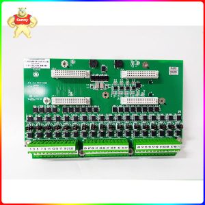
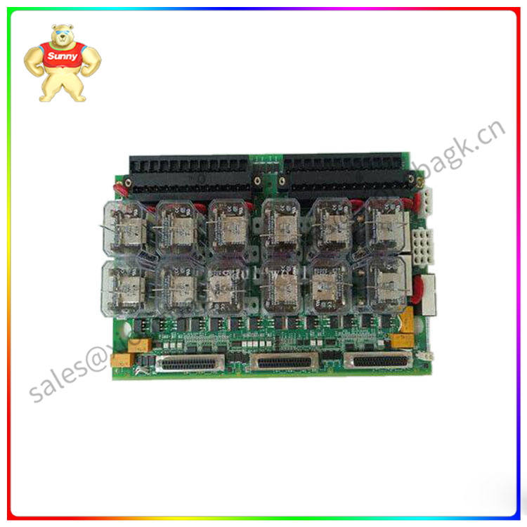
The IS200TREGH1BEC has a total of twelve relays on its surface. Nine of these are used to form three groups of three relays that vote upon inputs controlling trip solenoids. These relays have 28 VDC supplied from the VPRO board. Other board components include three (female) d-shell connectors for cable connections, two terminal strips, and several additional female plug connections. The board also has twelve metal oxide varistors, several wire jumpers, as well as integrated circuits and transistors. Components like resistors, diodes, and capacitors are mounted on both the front and rear surfaces of the board.
IS200TREGH1BEC
The IS200TREGH1BEC carries the board id, the GE logo, a barcode, and several other codes for identification. These help the user locate the proper manual or user guide for their particular part. For detailed information regarding the installation or maintenance of the IS200TREGH1BEC, please refer to these publications originally supplied by GE.
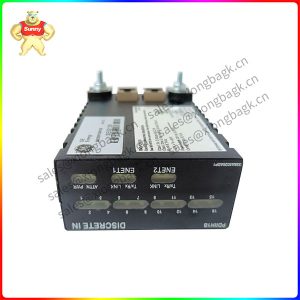
The IC660BBA104 is a Genius Analog I/O Block of GE Fanuc series 90-30 PLCs. It belongs to the Analog Mixed Modules group and can be powered with either 115 VAC or 125 VDC. It has four inputs and two outputs whose I/O range is between 4 mA to 20 mA and provides the system with different types of diagnostics. Circuits are isolated, and accuracy of input is as precise as 0.1%.
Power is provided to the block and all the circuits from a single input, so that external power is not needed to process signals. After the signal enters the block, circuits apply linear scaling to convert it to engineering units. With every scan, 8 bytes of data containing those engineering data are broadcasted. The output data broadcast in 4 bytes. The block provides an output that connects to a Bus Switching Module (IC660BSM21) and is compatible with Genius Bus Controllers, PCIM and QBIM modules. To configure the IC660BBA104 Genius Analog I/O Block, the user needs a Hand-held monitor version 3.7 or later. The programming software is Logicmaster 6 ver. 4.02 or later. CPUs that are compatible with the block are rev. 105 or later for Series Six PLCs and rev. 3.0 or later for series 5 PLCs.
The block can be configured to detect input alarms, hold the last output state, or a default state and receive output feedback. The time to convert a signal to a value can be up to 400ms, and the block can work if there is CPU redundancy. Diagnostic checks involve detection of input open wire, input high and low alarms for each input individually, I/O over range and under range signal detection, and errors in output feedback. The IC660BBA104 Genius Analog I/O Block has 32 terminals. The power source connects to terminals 5 and 6. I/O cables connect to the self-powered inputs 17 to 32. Outputs connect to terminals 11-12 and 14-15. If they are both grounded, a 10-ohm resistor is needed to prevent circuit damage. The bus switching module connects to terminals 9-10.
Please contact Sunny sales@xiongbagk.cn for the best price.
➱ sales manager: Sunny
➱ email mailto: sales@xiongbagk.cn
➱ Skype/WeChat: 18059884797
➱ phone/Whatsapp: + 86 18059884797
➱ QQ: 3095989363
➱ Website:www.sauldcs.com