中文版
中文版


Description
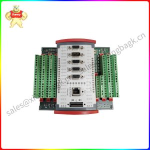
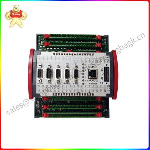
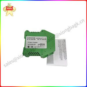
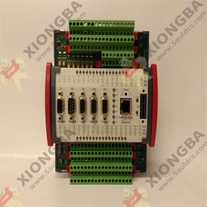
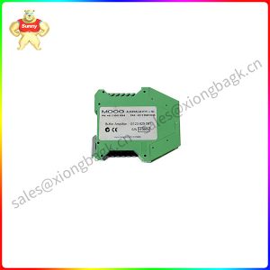
G122-829-001 P-I Servoamplifier G122-829A001
Product description
Inputs 1, 2 and feedback go to the error amplifier and can be used for feedback or command. Care needs to be taken in selecting signal polarity to achieve negative feedback for the overall closed loop. Since the input error amplifier sums the signals, the transducer feedback signal needs to be the opposite polarity of the command. This can be achieved in two ways:
Arrange for an opposite polarity feedback transducer signal and connect it to input 1, input 2 or the positive feedback amplifier input.
If the feedback transducer signal is the same polarity as the command, you only have one option: Connect it to the negative input of the feedback amplifier.
The servoamplifier has a unity gain input error amplifier followed by two parallel stages, one a proportional amplifier and the other an integrator. The outputs of these two stages can be switched to the output power amplifier (see paragraph 7 above) which then drives the valve.
The input to the integrator stage can be switch selected (SW4:1) from either the output of the error amplifier, I in = E, or the output of the proportional stage, I in = P. The latter arrangement is used in the G122-202. It is beyond the scope of these Application Notes to detail the benefits of each arrangement. If you have experience with the G122-202, I in = P would seem to be an easy choice.

G122-829-001
Product parameter
1 Scope
These Application Notes are a guide to applying the G122-829A001 P-I Servoamplifier. These Application Notes can be used to:
Determine the closed loop structure for your application.
Select the G122-829A001 for your application. Refer also to data sheet G122-829.
Use these Application Notes to determine your system configuration.
Draw your wiring diagram.
Install and commission your system.
Aspects, such as hydraulic design, actuator selection, feedback transducer selection, performance estimation, etc. are not covered by these Application Notes. The G122-202 Application
Notes (part no C31015) cover some of these aspects. Moog Application Engineers can provide more detailed assistance, if required.
Application field
2 Description
The G122-829A001 is a general purpose, user configurable, P-I servoamplifier. Selector switches inside the amplifier enable either proportional control, integral control, or both to be selected. Many aspects of the amplifier’s characteristics can be adjusted with front panel pots or selected with internal switches. This enables one amplifier to be used in many different applications. Refer also to data sheet G122-829.
3 Installation
3.1 Placement
A horizontal DIN rail, mounted on the vertical rear surface of an industrial steel enclosure, is the intended method of mounting. The rail release clip of the G122-829A001 should face down, so the front panel and terminal identifications are readable and so the internal electronics receive a cooling airflow.
An important consideration for the placement of the module is electro magnetic interference (EMI) from other equipment in the enclosure. For instance, VF and AC servo drives can produce high levels of EMI. Always check the EMC compliance of other equipment before placing the G122-829A001 close by
widely used in smart home, logistics management, environmental monitoring and other fields.
Please contact Sunny sales@xiongbagk.cn for the best price.
➱ sales manager: Sunny
➱ email mailto: sales@xiongbagk.cn
➱ Skype/WeChat: 18059884797
➱ phone/Whatsapp: + 86 18059884797
➱ QQ: 3095989363
➱ Website:www.sauldcs.com