中文版
中文版

Description
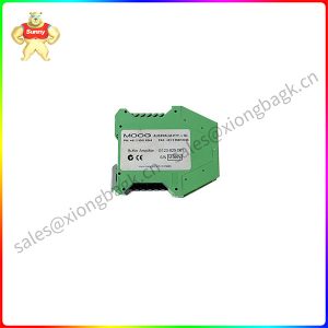
G123-815A001 Buffer Amplifier G123-815
Product description
1 Scope
These application notes are a guide to applying the G123-815Buffer Amplifier. They tell you how to install, connect andadjust the Buffer Amplifier. They do not tell you how to designthe closed loop system in which it is used.
2 Description
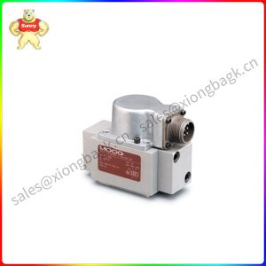
The G123-815 Buffer Amplifier interfaces between standardPLC analogue input and output modules, on one side, anda position transducer and a oog valve, on the other.It simplifies the use of a PLC in closing position loops.The Buffer Amplifier solves the common problem of the+10V PLC output being incompatible with the valve driverequirements. lt also provides digital noise filtering for the valvesignal and noise filtering for the position transducer signal.For a more detailed description, see Moog brochureG123-815E01.01.
3 Installation
3.1 Placement
A horizontal DlN rail, mounted on the vertical rear surface ofan industrial steel enclosure, is the intended method ofmounting. The rail release clip of the G123-815 should facedown, so the front panel and terminal identifications arereadable and so the internal electronics receive a coolingairflow, An important consideration for the placement of themodule is electro magnetic interference (EMl) from otherequipment in the enclosure. For instance, Vf and AC servodrives can produce high levels of EMl. Always check the EMCcompliance of other equipment before placing the G123-815close by.犖

Product parameter
Valve drive input:Valve drive outputs:0 to ± 10V
Valve drive currentselections:0 to ± 10v @ 1K Ohm min0 to ± 100mA maxmax losd=( amo-39) ohm
Valve drive test point:+5, 10, 20, 30 & 50 mA
Probe test point:Zo=10K Ohm
VV LED:Zo =10K Ohm
Iv LED:Maximum illumination at±10V+=red
Valve filter type:MMaximum illumination at+5 mA\+100mA+=red
Active, single pole
Application field
5.1 Digital noise filter
This filter removes the digital quantization noise, due to thePLC update period, in the PLc output signal. Because PLC’s canhave low frequency period noise that the valve can respond to,it is important to remove this update rate noise so the valvedoes not buzz and the load does not follow. The updateperiod of the PLc needs to be known so the correct filter timeconstant can be selected. Initially set the filter period to beequal to the update rate. Switch values sum, so if you need15mS, select 10 and 4.7
When the system is operating, a final check of the timeconstant can be made.lf the valve buzzes, a greater timeconstant is required. lf the valve does not buzz, reduce thetime constant until buzzing is detected, then increase it untilthe buzzing just stops.
To calculate the 3dB freguency roll off point, use the formula:f= 159 Hz, where T = the sum of mS period switches selected
5.2 Low Rin
The “low Rin” switch drops the input resistance for the PLCsignal from 100k Ohm to 1k Ohm. This can improve the noiseimmunity of the signal. Be sure the PLC output can deliver+10mA that is needed when low Rin is selected.
5.3 Valve drive signal
Select the output signal to match the valve requirement.If voltage is selected, the ± 10v output can drive up to ±10mA. lf current is selected, the full scale current output willthen need to be selected on the valve current switches. Theswitches sum, so if 45mA is reguired, select 30, 10 and 5mA.Maximum output current, in current mode.is +100mA.
Please contact Sunny sales@xiongbagk.cn for the best price.
➱ sales manager: Sunny
➱ email mailto: sales@xiongbagk.cn
➱ Skype/WeChat: 18059884797
➱ phone/Whatsapp: + 86 18059884797
➱ QQ: 3095989363
➱ Website:www.sauldcs.com