中文版
中文版

Description
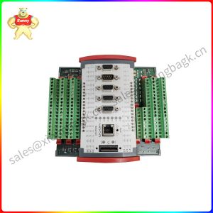
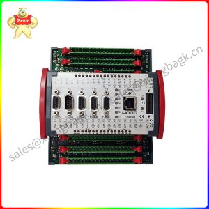
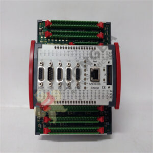
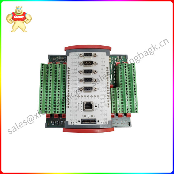
Product Overview: MOOG D136-003-001 Servo Valve
1. General Description
The Moog D136-003-001 is a high-performance, two-stage electro-hydraulic servo valve. This model is a core component in closed-loop control systems, where precise and high-speed control of hydraulic flow and pressure is required. It translates a low-power electrical input signal into a high-power hydraulic output with exceptional accuracy and dynamic response.
Servo valves of this type are critical in applications where the position, velocity, or force of a hydraulic actuator must be controlled with extreme precision. The D136 series is known for its reliability and performance in demanding industrial and aerospace environments.
2. Key Features and Functions
- Operating Principle: The valve operates in two stages:
- First Stage (Torque Motor & Flapper/Nozzle): A low-current electrical signal (e.g., ±10 mA) is applied to the torque motor coils. This creates a magnetic force that deflects a flexure tube and a connected flapper positioned between two nozzles. This movement creates a differential pressure.
- Second Stage (Spool Valve): The differential pressure from the first stage acts on the ends of a four-way sliding spool. The spool shifts, precisely directing hydraulic fluid to (and from) a single or double-acting hydraulic actuator.
- High Precision and Resolution: Provides extremely fine control over fluid flow, allowing for smooth and accurate actuator movement even at very low speeds.
- Fast Dynamic Response: Designed for high-frequency operation, enabling rapid system response to changing command signals. This is critical for applications requiring high bandwidth.
- Null Shift Adjustment: Features an external adjustment mechanism to mechanically bias the spool and correct for null drift, ensuring the valve output is zero when the input signal is zero.
- Robust Construction: Built to withstand harsh operating conditions, including vibration, contamination levels typical of industrial systems, and a wide range of operating temperatures.
- Filtered Protection: The valve includes an integral, micron-rated inlet filter to protect its critical internal components from particulate contamination, which is a primary cause of valve failure.
3. Technical Specifications
The following specifications are typical for the D136 series. For exact values of the -003-001 variant, consulting the official datasheet is essential.
| Parameter | Typical Specification | Notes |
|---|---|---|
| Model Type | Two-Stage, Flow Control Servo Valve | Flapper-nozzle pilot stage, 4-way main stage spool. |
| Actuator Type | Permanent Magnet Torque Motor | |
| Input Signal | ±10 mA (or commonly ±8 mA for some variants) | The -003 likely denotes this specific input/performance rating. |
| Input Impedance | ~200 Ω @ 25°C (for ±10 mA coil) | |
| Null Pressure | 50% of supply pressure (Ps) | For equal area actuators. |
| Rated Flow (Q_nom) | Varies by model (e.g., 5, 10, 15, 20 GPM) | The -001 suffix often specifies a 5 GPM rated flow at 1000 psi drop. |
| Supply Pressure (Ps) | Up to 3000 psi (210 bar) | Standard maximum operating pressure. |
| Hysteresis | < 3% | |
| Threshold | < 1% | |
| Frequency Response (-3 dB) | > 100 Hz | At 50% rated current. |
| Porting Size | SAE-10 (for 5 GPM model) | Inlet, Control, and Return ports. |
| Hydraulic Fluid | Mineral-based petroleum oils per MIL-PRF-5606 or MIL-PRF-83282 | Compatible with standard industrial hydraulic fluids. |
| Fluid Temperature Range | -65°F to +275°F (-54°C to +135°C) | |
| Filtration Requirement | 10 micron absolute | Critical for reliability. The internal filter is a last line of defense. |
4. Ordering Code Breakdown: D136-003-001
- D136: The base model number for this family of servo valves.
- -003: This typically denotes a specific electrical configuration (e.g., ±10 mA input, specific coil impedance and connector type).
- -001: This almost universally specifies the rated flow capacity of the valve. In the D136 series, -001 commonly corresponds to a 5 US Gallons Per Minute (GPM) flow rating at a 1000 psi (70 bar) pressure drop across the valve.
Note: Other common flow suffixes include -002 (10 GPM), -003 (15 GPM), and -004 (20 GPM). It is crucial to verify this, as the “003” in the middle of this part number is for the electrical side, not the flow.
5. Typical Applications
The Moog D136 servo valve is used in a wide array of high-performance motion control systems:
- Industrial Automation: Precision machine tools (grinders, EDMs), injection molding machines, rolling mills.
- Test and Simulation: Fatigue testing systems, flight simulators, structural test rigs.
- Aerospace: Flight control surface actuators (in some aircraft), fuel control systems, ground support equipment.
- Robotics: High-force, precision hydraulic robotic actuators.
6. Important Note
- The Moog D136 is a classic and widely used servo valve design. Many variants exist with different electrical inputs (e.g., ±10 mA, ±40 mA, ±100 mA, ±10 VDC) and flow ratings.
- The information provided is based on the standard D136 series. The exact specifications for the D136-003-001 can only be confirmed by consulting the official Moog technical data sheet (TDS) or product manual for that specific part number. Proper installation, commissioning, and maintenance are critical for the performance and longevity of high-precision servo valves.
Please contact Sunny sales@xiongbagk.cn for the best price.
➱ sales manager: Sunny
➱ email mailto: sales@xiongbagk.cn
➱ Skype/WeChat: 18059884797
➱ phone/Whatsapp: + 86 18059884797
➱ QQ: 3095989363
➱ Website:www.sauldcs.com