

Description
5SHY3545L0016 3BHB019719R0101 GVC736BE101 91MM IGCT MODULE
Avoid personal injury or property damage from sudden release of process pressure or bursting of parts.
Before performing any maintenance operations:
Always wear protective clothing and eyewear. Disconnect any operating lines providing air pressure, electric power,
or a control signal to the actuator. Be sure the actuator cannot suddenly open or close the valve.
Use bypass valves or completely shut off the process to isolate the valve from process pressure. Relieve
process pressure from both sides of the valve. Drain the process media from both sides of the valve.
Vent the pneumatic actuator loading pressure and relieve any actuator spring precompression.
Use lock-out procedures to be sure that the above measures stay in effect while you work on the equipment.
Check with your process or safety engineer for any additional measures that must be taken to protect against process media.
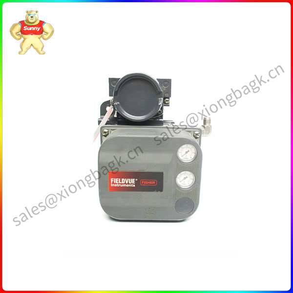
DVC6010
Refer to figures 1 and 2 for mounting parts identification. Refer to the FIELDVUE DVC5000 Series Digital Valve Controllers Instruction Manual –
Form 5335 for DVC5010 digital controller parts identification, and the FIELDVUE DVC6000 Series
Digital Valve Controllers Instruction Manual – Form 5647 for DVC6010 digital valve controller part
identification. Refer to the appropriate actuator instruction manual for actuator installation, operation, maintenance and parts identification.
1. Isolate the control valve from the process line pressure, release pressure from both sides of the
valve body, and drain the process media from both sides of the valve. Shut off all pressure lines to the actuator, releasing all pressure from the actuator.
Use lock-out procedures to be sure that the above measures stay in effect while you work on the equipment.
2. Attach the connector arm (key 108) to the valve stem as follows:
On actuators without side-mounted handwheel, refer to figure 1.
a. Remove one of the stem connector screws.
Insert one of the cap screws (key 120) included in the kit through the connector arm (key 108) and start it in the stem connector. Tighten the screw
so that the stem connector clamps the valve and actuator stems but still permits the connector arm to be moved.
b. Remove the second stem connector screw.
Swing the connector arm into place and start the second screw (key 120) from the kit. Tighten both screws.
On actuators with side-mounted handwheel refer to figure 2. Loosen the lock nut below the travel
disc. Insert the connector arm beneath the travel disc and tighten the lower lock nut against the connector arm.

Please contact Sunny sales@xiongbagk.cn for the best price.
➱ sales manager: Sunny
➱ email mailto: sales@xiongbagk.cn
➱ Skype/WeChat: 18059884797
➱ phone/Whatsapp: + 86 18059884797
➱ QQ: 3095989363
➱ Website:www.sauldcs.com


Reviews
There are no reviews yet.