

Description
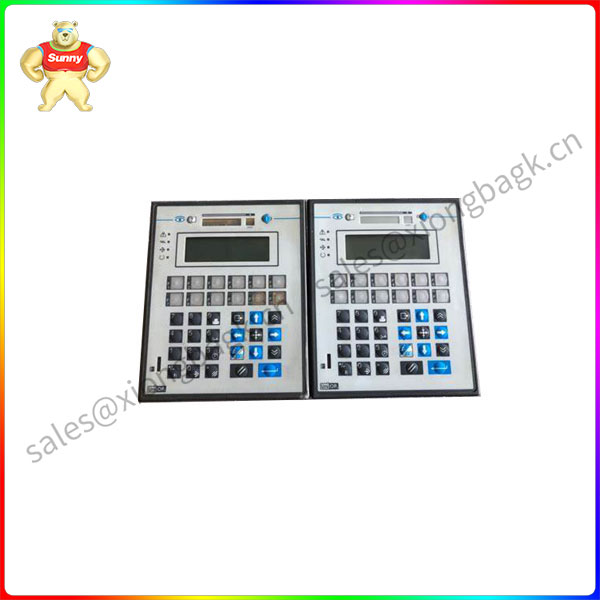
EK52 6ZA963-7 Universal Operator Panels
UniOP panels are designed to be mounted on the front of some type of enclosure. The
bezel height, bezel width and the cut-out dimensions for each panel type are given in
the following pages.
The unit must always be grounded to earth. Grounding helps limit the effects of noise
due to electromagnetic interference on the control system.
Earth connection will have to be done using either either the screw or the faston
terminal located near the power supply terminal block. A yellow label help identify
the ground connection. Also connect to ground the terminal 3 on the power supply
terminal block.
The power supply circuit may be floating or grounded. In the latter case connect to
ground the power source common as shown in figure 42 with a dashed line.
When using the floating power scheme, note that the panels internally connect the
power commond to ground with a 1 MΩ resistor in parallel with a 4,7 nF capacitor.
The power supply must have double or reinforced insulation
The suggested wiring for the power supply is shown in figure 36.
EK52 6ZA963-7
The PLC Port is used to communicate with the PLC or with another type of
controller; if the panel is configured as an UniNET client, then this port may be used
for the network connection.
Different electrical standards are available for the signals in the PLC port connector:
RS-232, RS-422, RS-485 or Current Loop 20 mA. The cable used selects the
appropriate signals. It is always necessary to use the correct cable type for on the PLC
to be connected.
The function of the PC/Printer Port depends on the mode of operation of the panel.
Configuration Mode programming port
Operation Mode, UniNET Server connection to UniNET
Operation Mode, UniNET not active or Client node connection to serial printer
Only RS232 signals are available on the PC/Printer Port. The connector is a D-15 pin
female. Pin assignment is shown in the table below.
The procedure to mount the communication modules is the following:
1) turn off the unit
2) partially unscrew with a screwdriver the 2 screws holding the rear cover. The
screws are labelled ‘A’ in Figure 44
3) remove the cover (for eTOP05/05EB/06/06C/20C/33C/40C/50C and ePAD33C
lever with screwdriver on the slot on the cover’s side).
4) plug the module in the red connectors; make sure the connectors are locked
5) replace the rear cover
6) fix the 2 screws ‘A’ (for eTOP05/05EB/06/06C/20C/33C/40C/50C and ePAD33C
close the cover with a little pressure).
7) stick in the area ‘B’ the label describing the functionality of the AUX Port. The
label is delivered with the modules


Please contact Sunny sales@xiongbagk.cn for the best price.
➱ sales manager: Sunny
➱ email mailto: sales@xiongbagk.cn
➱ Skype/WeChat: 18059884797
➱ phone/Whatsapp: + 86 18059884797
➱ QQ: 3095989363
➱ Website:www.sauldcs.com


Reviews
There are no reviews yet.