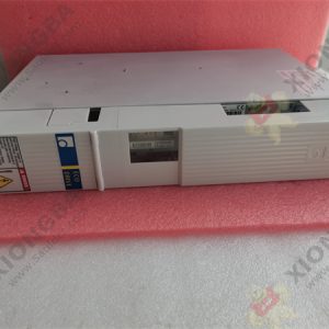
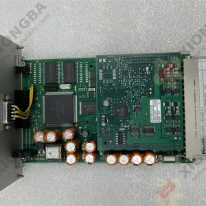
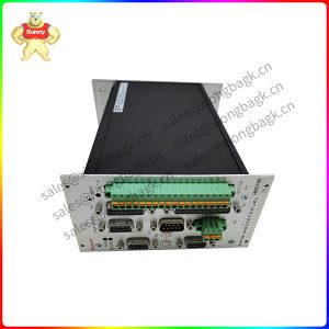
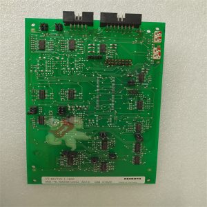
Description
Product details:
Automatic control system of VT-MVTW-1-16/D driver module digital closed-loop control panel based on
feedback principle. The so-called feedback principle is to control according to the changing information
of the system output, that is, by comparing the deviation between the system behavior (output) and the
expected behavior, and eliminating the deviation to obtain the expected system performance.
VT-MVTW-1-16/D In the feedback control system, there is a signal forward path from the input to the
output and a signal feedback path from the output to the input, which forms a closed loop.
Therefore, VT-MVTW-1-16/D feedback control system is also known as closed-loop control system. Feedback
control is the main form of automatic control. Most automatic control systems are feedback control systems. In
engineering, the feedback control system which keeps the output consistent with the expected value in operation is
often called automatic regulation system, and the feedback control system which is used to precisely follow or realize a certain process is called servo system or servo system.
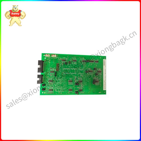
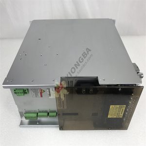
VT-MVTW-1-16
VT-MVTW-1-16/D feedback control system is composed of controller, controlled object and feedback path. The
comparison link is used to subtract the input from the output to give a deviation signal. In a specific system, this link
may be referred to together with the controller as the regulator. Take furnace temperature control as an example, the
controlled object is furnace; VT-MVTW-1-16/D output variable is the actual furnace temperature; The input variable is the
given constant temperature, which is generally expressed by voltage. The furnace temperature is measured by
thermocouple. The thermoelectric motive force representing the furnace temperature is compared with the given voltage. The
difference voltage between the two is used to drive the corresponding actuator for control after power amplification.
The basic composition of a typical feedback control system can be represented by the block diagram shown in Figure 1.8.
Components of the system are divided according to their functions in the system. There are mainly the following types:
(1) Given components: Input quantity corresponding to expected output is given.
(2) Comparison components: to find the input and feedback of the deviation, often use integrated operational amplifier
(referred to as integrated operational amplifier) to achieve.
(3) Amplification components: Because the deviation signal is generally small, not enough to drive the load, so the need for
amplification components, including voltage amplification and power amplification.
(4) Execution element: directly drive the controlled object, so that the output changes. Commonly used motor, regulating valve, hydraulic motor and so on.
(5) Measuring element: detect the controlled quantity and convert it into the required electrical signal. In the control
system commonly used for speed measurement generator, photoelectric coding disk and so on; Rotary transformers and
automatic machines for position and Angle detection; Transformers for current detection and thermocouples for temperature
detection, etc. These detection devices generally convert the detected physical quantity into the corresponding continuous or discrete voltage or current signal.
(6) Correction element: also known as compensation element, it is a component whose structure and parameters are easy to
adjust. It is connected in the system by series or feedback to complete the required calculation function and improve the
performance of the system. According to the different position in the system, they can be called series correction element and feedback correction element respectively.
Please contact Sunny sales@xiongbagk.cn for the best price.
➱ sales manager: Sunny
➱ email mailto: sales@xiongbagk.cn
➱ Skype/WeChat: 18059884797
➱ phone/Whatsapp: + 86 18059884797
➱ QQ: 3095989363
➱ Website:www.sauldcs.com