

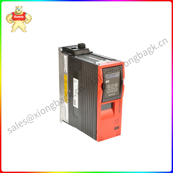
Description
MDS60A0040-5A3-4-00 MOVIDRIVE MD 60A
1.X1: Mains connection L1 (1)/L2 (2)/L3 (3), separable2.X4: DC link connection -Uz/ +Uz and PE
connection, separable3.X2: Motor connection U(4)/V(5)/W (6), separable4. Connection for power shield
clamp (not visible)5.X3: Braking resistor connection R+ (8)/R- (9) and PE connection, separable6.
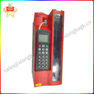
TERMINAL: Option slot for DBG11A keypad or USS21A serial interface
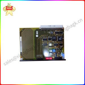
7. Control pcb on CONTROL option slot
8.X11: Electronics terminal strip (setpoint input Al1 and 10 V reference voltage)9. Switch S11 (signal type Al1)
and switch S12 (system bus terminating resistor)10.X12: Electronics terminal strip system bus (SBus)
11.7-segment display
12.X10: Electronics terminal strip binary outputs and TF/TH input13.X13: Electronics terminal strip binary
inputs and RS-485 interface14.0nly MDV/MDS, X14: Incremental encoder simulation or external encoder input (9.pin sub D plug)
15.0nly MDV/MDS, X15: Motor encoder input (9-pin sub D socket)
16.0PTION1 and OPTlON2: Option slots 1 and 2
17.Connection for electronics shield clamps
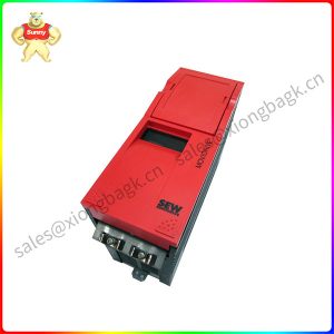
MDS60A0015-5A3-4-0T
Route power cables and electronics cables in separate cable ducts
Install the input fuses at the beginning of the supply system lead behind thesupply bus junction (-> Wiring
diagram for basic unit, power section and brake).Using an earth-eakage circuit breaker as the sole protection
device is notpermitted. Earth-eakage currents > 3.5 mA can arise during normal operation ofthe inverter.
Only use contactors in utilization category Ac-3 (lEC 158-1) as supply systemand brake contactors.
With a supply system lead < 10 mm? (AWG 8): Lay a second PE conductor withthe cross section of the supply
system lead in parallel to the protective earth viaseparate terminals or use a copper protective earth with a cross section of 10mm? (AWG 8).
With a supply system lead ≥ 10 mm’ (AwG 8): Lay a copper protective earthwith the cross section of the supply system lead.
SEW recommends using earth-eakage monitors with a pulse code measuringprocess in voltage supply systems
with a non-earthed star point (iT systems). Thisavoids mis-tripping of the earth-leakage monitor due to the earth capacitance of theinverter.


Please contact Sunny sales@xiongbagk.cn for the best price.
➱ sales manager: Sunny
➱ email mailto: sales@xiongbagk.cn
➱ Skype/WeChat: 18059884797
➱ phone/Whatsapp: + 86 18059884797
➱ QQ: 3095989363
➱ Website:www.sauldcs.com


Reviews
There are no reviews yet.