

Description
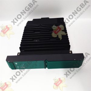
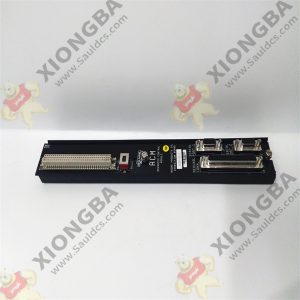
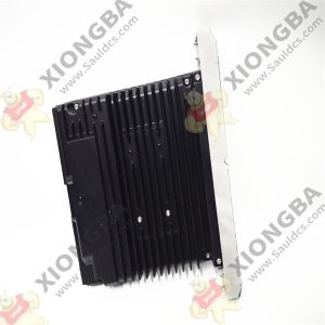
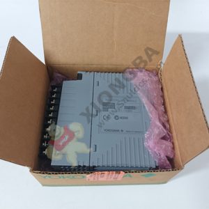
SDV144-S13/B4D00 Digital I/O Modules (for FIO)
If SDV144 field wiring diagnostic functions are used, the following diagnostic elements should be installed for
individual channels in the vicinity of the field equipment:
• SCB100 (for defective open circuit detection while accepting off signals) (*1)
• SCB110 (for defective short-circuit detection while accepting on signals) (*2)
*1: Input signals are normally off while in normal operation.
*2: Input signals are normally on while in normal operation.
When the input signals are normally off while in normal operation, connect the SCB100 in parallel with the contact
output of the field equipment as given below.
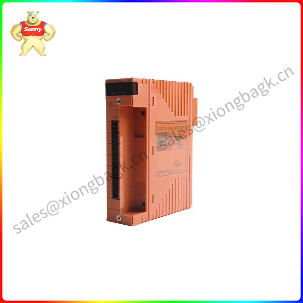
SDV144-S13
When the input signals are normally on while in normal operation, connect the SCB110 in series with the contact
output of the field equipment (take care about the polarity taking note of the polarity).
When checking for both defective short and open circuits, connect the SCB100 and SCB110 in parallel and series with
the contact outputs of the field equipment respectively, as given below.
Output modules output on/off status signals to field equipment.
The output modules can be made dual-redundant respectively. They incorporate field wiring diagnostic functions, so
they require no wiring diagnosis elements.
*1: These voltages show the case using the field power supply floating. When the field power supply is grounded, the system
(functional) ground is connected to the field ground, which is not isolated. For the higher noise immunity, floating the field
power supply is recommended.
*2: When the withstanding voltage of the field power supply between the secondary side and the ground is lower than the value
shown in the table above, these voltages are adopted as the withstanding voltage of the field power supply.
*3: Number of input channels which a user can use and external power supply are restricted in case of SDV144-SC.
Refer to “ProSafe-RS Outline of I/O Modules (for FIO)” (GS 32P06K60-01EN).
*4: The contact rating and the external power supply of SDV144 style code S1, S2 and S3 are 24 V DC ± 5 %.
*5: When connecting SDV144 and SED4D terminal board using the dedicated signal cable, the withstand voltage is 500 V AC
(between input signal lines and system). If MIL connector cables are used, the withstand voltage depends on their cable’s
electrical specifications.

Please contact Sunny sales@xiongbagk.cn for the best price.
➱ sales manager: Sunny
➱ email mailto: sales@xiongbagk.cn
➱ Skype/WeChat: 18059884797
➱ phone/Whatsapp: + 86 18059884797
➱ QQ: 3095989363
➱ Website:www.sauldcs.com


Reviews
There are no reviews yet.