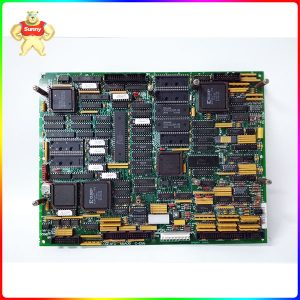
Jumper switches (J1 to J5) control the line current monitoring and generator/bus voltage monitoring functions on the DS200TCCBG3BCB board. Jumpers are also used to connect RS232 serial ports to DCOM (J14) and for testing (J15 and J16). The GE manual will provide additional information on jumper setup. [caption id="attachment_21151" align="aligncenter" width="550"] DS200TCCBG3BCB[/caption] DS200TCCBG3BCB board is
The DS200TCCBG3BCB is a board assembly in the GE Mark V turbine control system used as a general purpose extended analog I/O board. The board provides adjustment and scaling for analog I/O signals from the TBCB board. The board is located in the <r5> kernel.</r5> It also reads signals from the TCEB board located in
DS200TCCBG3A Because multiple ribbon cables may disconnect from the old board and reconnect to the replacement board, you may inadvertently connect them to the wrong connector on the new board. The problem is complicated by the fact that the replacement board may be an updated version of the old board. It may have connectors in
GE I/O TC2000 analog board DS200TCCBG2A has an 80196 microprocessor and several PROM modules. It also contains an LED and 2 50-pin connectors. The LED is visible from the side view of the board. The ID of the 50-pin connector is JCC and JDD. The PROM module stores the firmware and programming instructions of the
The General Electric I/O TC2000 analog board DS200TCCBG1B has an 80196 microprocessor and multiple PROM modules. It also contains an LED and 2 50-pin connectors. The LED is visible from the side view of the board. The ID of the 50-pin connector is JCC and JDD. The board is also equipped with three jumpers. The
GE I/O TC2000 analog board DS200TCCBG1ANE has an 80196 microprocessor and several PROM modules. The DS200TCCBG1ANE also contains an LED and 2 50-pin connectors. The LED is visible from the side view of the board. The ID of the 50-pin connector is JCC and JDD. Leds can be used to indicate whether the board is
DS200TCCBG1ALD Configuration: Hardware: The Mark V LM's generator and bus voltage monitoring capabilities, as well as line current monitoring capabilities, are provided by hardware jumpers J1, J2, J3, J4 and J5. The RS232 serial port is connected to the DCOM through the hardware jumper J14. J15 and J16 are the hardware jumpers used for testing.
GE I/O TC2000 analog board DS200TCCBG1ALD has an 80196 microprocessor and several PROM modules. It also contains an LED and 2 50-pin connectors. The LED is visible from the side view of the board. The ID of the 50-pin connector is JCC and JDD. The PROM module stores the configuration file of the microprocessor and
GE I/O TC2000 analog board DS200TCCAG2B has an 80196 microprocessor and multiple PROM modules. It also contains an LED and 2 50-pin connectors. The LED is visible from the side view of the board. The ID of the 50-pin connector is JCC and JDD. The GE I/O TC2000 analog board DS200TCCAG1B is also equipped with
GE I/O TC2000 analog board DS200TCCAG2A has an 80196 microprocessor and multiple PROM modules. It also contains an LED and 2 50-pin connectors. The LED is visible from the side view of the board. The ID of the 50-pin connector is JCC and JDD. The GE I/O TC2000 analog board DS200TCCAG1B is also equipped with