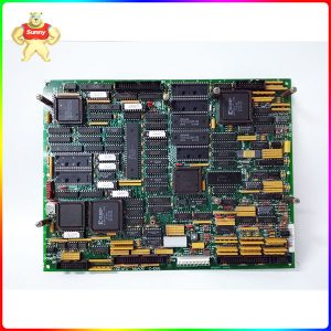
GE I/O TC2000 analog board DS200TCCAG1B has an 80196 microprocessor and multiple PROM modules. It also contains an LED and 2 50-pin connectors. The LED is visible from the side view of the board. The ID of the 50-pin connector is JCC and JDD. The GE I/O TC2000 analog board DS200TCCAG1B is also equipped with
GE I/O TC2000 analog board DS200TCCAG1A has an 80196 microprocessor and multiple PROM modules. It also contains an LED and 2 50-pin connectors. The LED is visible from the side view of the board. The ID of the 50-pin connector is JCC and JDD. Because the GE I/O TC2000 analog board DS200TCCAG1A is equipped with
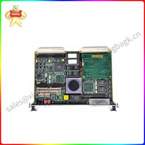
The DS200TBSAG1AAA is part of a variety of printed circuit boards developed as internal components of the Speedtornic Mark V Series industrial power generation turbine system. The MK V is one of a series of industrial turbine control systems from General Electric. The unit is one of the printed circuit boards designated as LM transducer
DS200TBSAG1A is one of a number of circuit board modules that can be used in the Speedtronic Mark V turbine based application module. The DS200 series printed circuit board is an internal component of the Mark V Series mount that allows processing and execution of a variety of applications. [caption id="attachment_21219" align="aligncenter" width="450"] DS200TBSAG1A[/caption] The
GE Gas Turbine terminal board DS200TBQGG1A has 2 terminals. Each block contains 95 signal line terminals. The GE Gas Turbine terminal board DS200TBQGG1A also contains 2 jumpers and 6 34-pin connectors. The board is 11.25 inches wide and 3 inches high and contains five holes for attaching the board to the inside of the drive.
The GE RST LM6000 analog board DS200TBQEG1B has two wiring terminals. Each block contains 95 signal line terminals. The GE RST LM6000 analog board DS200TBQEG1B also contains 2 jumpers and 6 34-pin connectors. The 34-pin connector has an ID associated with it on the board surface. A set of 34-pin connectors are JQQR, JQQS, and
The GE RST extended analog terminal board DS200TBQDG1AFF has two wiring terminals. Each block contains 107 signal line terminals. The GE RST extended Analog terminal board DS200TBQDG1AFF also contains multiple test points, two jumpers, and three 34-pin connectors. The GE RST Extended analog Terminal Board DS200TBQDG1AFF is equipped with three test points that qualified service
The GE RST analog terminal board DS200TBQCG1B has two wiring terminals. Each block contains 83 signal line terminals. The GE RST analog terminal board DS200TBQCG1B also contains 15 jumpers, three 40-pin connectors, and three 34-pin connectors. Because there are multiple 40 - and 34-pin connectors, the guidelines for connecting and disconnecting ribbon cables must be
The GE RST analog terminal board DS200TBQCG1A has two wiring terminals. Each block contains 83 signal line terminals. The GE RST analog terminal board DS200TBQCG1ABB also contains 15 jumpers, three 40-pin connectors, and three 34-pin connectors. The board is 11.25 inches long and 3 inches high and is designed for installation in a cabinet. Each
GE RST analog terminal board DS200TBQCG1AAA has two wiring terminals. Each block contains 83 signal line terminals. The GE RST analog terminal board DS200TBQCG1AAA also contains 15 jumpers, three 40-pin connectors, and three 34-pin connectors. Jumpers enable service personnel to modify the behavior of the board to meet the exact requirements of driver operation. When