

Description
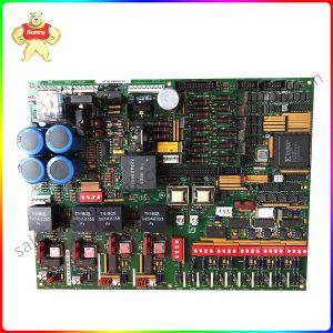
DS200CDBAG1ABA CONTACTOR DRIVER BOARD
Part Number: DS200CDBAG1A
Manufacturer: General Electric
Series: Driver Control
Functional Description: Contactor Driver Board
Availability: In Stock
Fuse: 4 amp 125V
Test points: 3
LED indicator: 1
Repair: 3-7 Days
Product Type: PCB
Manual: GEI-100182B
Country of Manufacture: United States (USA)
Functional Description
DS200CDBAG1A is a Contactor Driver Board developed by GE. It is a part of Driver Control control system.
component provides power to the Power Supply Board or DC Power Supply and Instrumentation Board to open and
close a contactor . The coil voltages of the contactors range from 30 to 40 V dc. The module closes a contactor by
applying 105 V dc for 250 msec to force the contactor closed. To keep the contactor closed, the board regulates the contactor
drive current at the level set using pot RV1. Three test points, a fuse, wiring connectors, configurable jumpers, an LED
indicator, and a potentiometer are included on this component. These features give the user a lot of control and enable
application-specific customization. The pot allows users to control the current of the contactor driver. Jumpers are used to
select coordinated operations. Users can check voltage signals using test points. This board transmits and receives
output signals via three plug connectors and a terminal board. More information about connector location can be found in
associated manuals. This board includes a potentiometer for adjusting the contactor driver current. This is typically set to 1.5 amps.

DS200CDBAG1ABA
Features
- When replacing the board, set pot RV1 on the new (replacement) board to the same position as on the
- replaced board. Failure to adjust the pot on DS304-type contactors may cause the contactor coil to fail.
- Testpoints are all referenced at CDBA common (ACOM), which is not the same as drive common. As a result,
- all test measurements must be carried out using isolated test equipment capable of measuring floating potentials.
- When the coordinated operation is chosen, an LED displays the status of the local contact close command.
- The input power is fused by FU1 and used to power the board from 75 to 140 V ac/dc. The coil voltages
- of the contactors must be between 30 and 40 V dc.
- It connects the drive control to a high-speed contactor, allowing for quick dropout protection in the drives.
- There are three testpoints. The testpoints allow the REFA voltage signal +15 V DC power supply to be checked. Three
- test points, a fuse, wiring connectors, configurable jumpers, an LED indicator, and a potentiometer are included on this Board.
- These features give the user a lot of control over the product and enable application-specific customization. The
- pot allows users to control the current of the contactor driver. Jumpers are used to select coordinated operations.
- Users can check voltage signals using test points. More information on these devices, including information on the
- board’s protective fuse, can be found in the associated manuals. Regardless, the versatility of this board makes it a highly desirable and well-designed PCB.


Please contact Sunny sales@xiongbagk.cn for the best price.
➱ sales manager: Sunny
➱ email mailto: sales@xiongbagk.cn
➱ Skype/WeChat: 18059884797
➱ phone/Whatsapp: + 86 18059884797
➱ QQ: 3095989363
➱ Website:www.sauldcs.com


Reviews
There are no reviews yet.