

Description
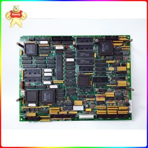
HE700GEN200 VME Interface Module
Product Description
1.1 Module Placement
The HE700GEN100/200 is considered a single slot generic VME module. If the interrupt capabilities of
this board are to be used, it must be placed in the interrupt chain. If not, it should be placed after all
modules that are utilizing VME interrupts.
1.2 Wiring Considerations
Normally, a GE Fanuc programmable controller runs the network, through a PLC module called a Genius
Bus Controller (GBC). The HE700GEN100/200 has the ability to replace or exist in conjunction with a
Genius Bus Controller. Up to 32 devices are wired in a daisy chained fashion. Network devices support
four communications terminals, Serial 1, Serial 2, Shield In and Shield Out. The network is terminated at
each end with an appropriate terminating resistor. The value of the resistor should be chosen to match
the characteristic impedance of the cable. Refer to GE Fanuc Automation publication GFK-90486 for
help in selecting an appropriate cable type for your application. Note: If the characteristic impedance of
the cable is unknown, 120 ohm terminating resistors should be used.
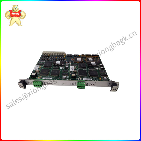
HE700GEN200
1.3 Dip Switch Location
There are several switches on the HE700GEN100/200 board that are used to configure the Genius
Interface, I/O addresses, Interrupts and User Mode. Figure 1.3 shows the location of these switches.
This chapter discusses the configuration of an HE700GEN100/200 uGENI VME Interface Module for
operation in a generic VME rack, and for Genius communications.
2.1 Genius Configuration
The configuration for each uGENI board is independent. There is one 8 position dip switch for each
uGENI board. Dip Switch 2 sets up the Genius configuration for uGENI 1 and Dip Switch 3 sets up the
Genius configuration for uGENI 2 (see Figure 1.3 on page 10). Below is the description of the dip switch
positions


Please contact Sunny sales@xiongbagk.cn for the best price.
➱ sales manager: Sunny
➱ email mailto: sales@xiongbagk.cn
➱ Skype/WeChat: 18059884797
➱ phone/Whatsapp: + 86 18059884797
➱ QQ: 3095989363
➱ Website:www.sauldcs.com


Reviews
There are no reviews yet.