


Description
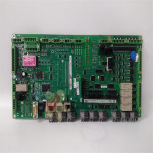
PP885R 3BSE069296R1 High performance operating panel
– Connect cable A.
– Connect cable B, using an M5 screw and a grounding conductor (as short as possible), that is sized correctly according to local electrical codes.
– Connect cable C.
– Connect cable D. The recommended cross-section of the cable is 1.5 mm2..

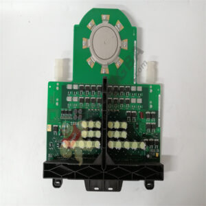
PP885-3BSE069276R1
The mounting clamps of the operator panel do not provide a secure grounding connection between the panel and the device cabinet, see 1 in drawing above.
1. Connect a wire, that is sized correctly according to local electrical codes, between the quick-connect terminal connector on the operator panel and the
chassis of the panel, see 2 in drawing above.
2. Connect a wire or grounding braid, that is sized correctly according to local electrical codes, between the chassis of the operator panel and the closest
grounding point on the door, see 3 in drawing above.
3. Connect a strong but short grounding braid between the door and the device cabinet, see 4 in drawing above.
4. Twist the cables onto the 24 V DC feed, see 5 in drawing above.
2 turns around the ferrite core provide 4 times the suppression of 1 turn.
3 turns around the ferrite core provide 9 times the suppression of 1 turn.
A ferrite core suppresses disturbances to the 24 V feed, see 6 in drawing above.
The grounding wires should be short and the conductor should have a large area.
A long, thin grounding wire has a very high impedance (resistance) at high frequencies and does not guide disturbances to the ground.
Multi-wire conductors are better than single wire conductors with the same area.
A braided conductor wire with the same area is even better. The best is a short, thick grounding braid.
Please contact Sunny sales@xiongbagk.cn for the best price.
➱ sales manager: Sunny
➱ email mailto: sales@xiongbagk.cn
➱ Skype/WeChat: 18059884797
➱ phone/Whatsapp: + 86 18059884797
➱ QQ: 3095989363
➱ Website:www.sauldcs.com